Current Channel Settings
This button allows the user to specify settings that will vary the
channel discharge and the related channel geometry and upland ridge
and subridge morphology specific to the subwatershed active in the
Channels tab current channel name box. The settings are
organized on two tabs, Geometry and Watershed. The Geometry
tab has settings for maximum velocity, upstream slope, downstream
slope, width to depth ratio, sinuosity, random scale factors on
sinusoidal channel, subridge spacing on sinusoidal channel, and
channel head and mouth elevation. The Watershed tab has
settings for runoff coefficient when using the Rational Runoff
Method (the default method), or to allow input of discharge
computed by an alternate method, and to add runoff from contiguous
land areas.
Command Prompt:
(blank, dialog box appears)
Left-clicking on the "Settings" button brings up the "Channel
'xxxx' Settings" dialog box that gives the user the options shown
below. The optional settings made in the "Channel 'xxxx'
Settings" dialog box will apply only to the Channel 'xxxx'
subwatershed. The blue subject bar at the top of the dialog
box displays the name of the channel's subwatershed to which the
Settings will apply. The user will select a different channel
in the "Current Channel" window of the "Channels" tab and then
left-click on "Settings" to make these changes to other channels
and their subwatersheds, e.g., 'Channel yyyy', 'Channel zzzz,"
etc. After specifying the settings in the dialog box,
the user can apply them by left-clicking the "OK" button at the
bottom of the dialog box.
Geometry tab
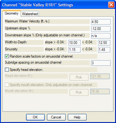 Maximum Water Velocity (ft./s.):
The user can specify a maximum water velocity for the channel by
typing the desired value into the edit box. Velocity
is inversely related to channel cross-sectional area
for a given discharge according to the relationship Q/a=v, where Q
is discharge (cubic feet per second), a is area (square feet), and
v is velocity (feet per second).
Maximum Water Velocity (ft./s.):
The user can specify a maximum water velocity for the channel by
typing the desired value into the edit box. Velocity
is inversely related to channel cross-sectional area
for a given discharge according to the relationship Q/a=v, where Q
is discharge (cubic feet per second), a is area (square feet), and
v is velocity (feet per second).
Upstream slope %: The
user can specify the upstream slope for the channel using this edit
box. This feature can be used to vary the channel's
longitudinal profile that will join to a mouth slope dictated by
the receiving channel slope at their confluence. It can also
be used to tie into the upstream slope when the headwaters of the
channel are at the GeoFluv Boundary and join with an upstream
channel slope draining "Additional watershed area."
Downstream slope % (Only
adjustable on main channel.): The user can specify the
mouth slope for the main channel at the GeoFluv Boundary to join
smoothly to the downstream channel slope by typing the desired
slope into the edit box. If the Channel's tab Settings dialog
box is open for any tributary to the main channel, the edit box
will read "n/a."
Width-to-Depth, slope>-0.04:
xx.xx , <-0.04: xx.xx: The user can specify
width-to-depth ratios for channels with slopes greater and less
than -0.04 by typing the desired width-to-depth ratio into the edit
box. The default values are 10.00:1 for channels with greater
than -0.04 slope and 12.5:1 for channels with less than -0.04
slope.
Sinuosity, slope>-0.04: xx.xx , <-0.04:
xx.xx: The user can specify sinuosity for channels
with slopes greater and less than -0.04 by typing the desired
sinuosity into the edit box. The default values are 1.15 for
channels with greater than -0.04 slope and 1.48 for channels with
less than -0.04 slope.
Random scale factors on sinusoidal
channel: The meander pattern of the idealized draft
valley bottom channels (<-0.04) will be determined by
mathematical constants and thus will be very uniform, changing
(enlarging) as a function of flow (related to discharge) and valley
bottom orientation. Checking the 'Random scale factors on
sinusoidal channel' box will randomly vary the constant values,
within their acceptable ranges for stable channels, such that
radius of curvature, meander length, and meander belt width
vary. This random variation produces a more natural
appearance for the channel and related upland landforms.
Subridge spacing on sinusoidal
channel: This setting applies to channels with slopes
<-0.04. The lower-gradient channels, with slopes
<-0.04, may have an adjacent floodplain (or terrace) area and
the uplands landform may begin some distance from the channel
banks. The user can use this setting to create some of this
open floodplain or terrace area by increasing the spacing between
subridges. A subridge spacing setting of 3, for example, will
create a subridge on every third meander bend of the channel with
an opening for the floor of the subridge valley between these
subridges.
Note: The user must select odd-number spacing; specifying even
number spacing will result in all subridges and subridge valleys on
opposites sides of the valley. Even spacing can be made with
manual SurvCADD editing. The user can also manually add or
delete subridges, or vary subridge longitudinal profiles using
Natural Regrade's
longitudinal profile editors, to introduce more variation to the
draft GeoFluvTM
landform.
Specify head
elevation: The user can specify the head elevation for
any channel, rather than accepting an elevation that is
automatically determined from the Pre-disturbance file specified in
the Settings tab. The user checks the box to select this
option and then proceeds in one of two ways. The user can
type a desired headwater elevation into the Specify Head Elevation
field. Alternately, the user can left-click on the Pick
button and then identify a (COGO) point of the desired elevation on
the drawing. To use the Pick method, the user left-clicks the
cursor near the desired point and then, by moving the cursor
diagonally, creates a box around the point. The user
left-clicks again to define the opposite corner of the box
surrounding the desired point and the point elevation is entered
into the Specify Head Elevation field.
Specify mouth
elevation: The user can (and should) specify the mouth
elevation for the main channel only. This setting becomes
inactive on the tributary channels because their mouth elevation is
controlled by the main channel's longitudinal profile. The
procedures for setting the elevation are the same as in Specify
Head Elevation above.
[Note: The user should specify the mouth
elevation of the main channel in the GeoFluvTM
project area because this elevation and the channel slope
immediately downstream of this point may be the most critical variables for
assuring a stable landform design. The elevations that
Natural Regrade
interpolates from the 'Pre-disturbed surface' specified in the
Settings tab are appropriate for creating and comparing draft
design alternatives, but a channel mouth elevation interpolated
from a map surface can vary from the actual elevation on the order
of feet. A channel will be expected to adjust to elevation
and slope inaccuracies by erosion.]
Watershed tab
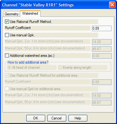
Use Rational Runoff Method: This is the default
setting for calculating runoff to the GeoFluvTM
channels in Natural
Regrade and is the setting that will be used when the box is
checked. The Rational Runoff Method calculates a peak
discharge using the formula Qpk = CIA, where C is the runoff
coefficient, I is the rainfall intensity, and A is the
acreage. The user enters the appropriate runoff coefficient
for the area within the GeoFluvTM
boundary in the Runoff Coefficient field and Natural Regrade does all the related
calculations.
Use manual Qpk: The
user can choose to input a peak discharge value calculated by some
other method should he wish by checking the 'Use Manual Qpk'
option. When the user checks this box, the runoff coefficient
field in the Use Rational Runoff Method setting (and use of that
method) becomes disabled. The user then types in the peak
discharges that he wants to use for the two storm events.
[Note: The GeoFluvTM
approach uses the 2-yr, 1-hour storm event to calculate bankfull
discharge and the 50-yr, 6-hr event to calculate a flood-prone
discharge. Reclamation landforms constructed using the
GeoFluvTM
approach that use these inputs have been stable in a very harsh and
erosive high-altitude desert environment through extreme storm
events. Using other input values may give unsatisfactory
results.]
Additional Watershed
Area: This setting allows the user to incorporate
runoff from contiguous lands into the GeoFluv Boundary. When
the user checks the Additional Watershed Area box, the fields below
become active and offer a choice of how the additional runoff will
enter the GeoFluv Boundary. If the head of the GeoFluvTM
channel is downstream of the Additional Watershed Area, as
when joining to an upstream channel reach, the user should
select the "At head of channel" option. The GeoFluvTM
channel's headwater dimensions will then be sized to accommodate
the runoff from the area above the channel headwaters within the
GeoFluv Boundary and the Additional Watershed
Area upstream of that. If the Additional Watershed Area is
subparallel to the GeoFluvTM
channel, checking "Evenly along length" will introduce the runoff
from the Additional Watershed Area gradually along the GeoFluvTM
channel reach and the channel dimensions will increase
proportionately along the reach. The remainder of the
settings are as described above in "Use Rational Method" and "Use
manual Qpk."