Use the command sctgrid using the .tin and
.mxs files to create the .xsct Reach Section file. Use the
command scto3dp to draw the Reach Section file onto the
surface.
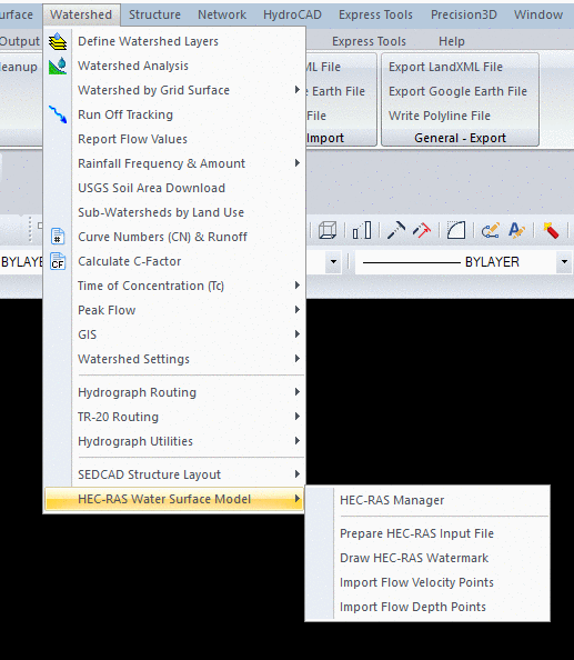
The command, hecras, may be typed in the
Command Ribbon or found in the Hydrology module, Watershed
dropdown, HEC-RAS Surface Model, HEC-RAS Manager.
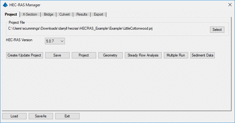
It is used for creating, managing and modifying HEC-RAS projects
directly from Carlson Hydrology. When executed, you will
select or create a .ras HEC-RAS Settings file. Once the .ras
file is chosen or created, the HEC-RAS Manager dialog
appears. Click the Select button to create a new HEC-RAS
project file or to select an existing project. Set the
HEC-RAS version by clicking the dropdown arrow and choosing the
version you downloaded and installed. The .ras settings file is
updated when the HEC-RAS Manager is closed using the "X" or the
exit button.
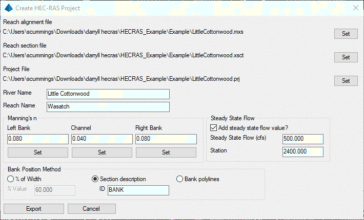
Select the Create/Update Project button to
update an existing project or to create a new one. When
clicked the Create HEC_RAS Project dialog appears. Use the
Set buttons to assign the Reach Alignment file, the Reach Section
file and the HEC-RAS project name. Fill in the River Name and
the Reach Name. Use the Set buttons to assign the Manning's
friction coefficient (n) to the banks and bottom of the
channel. Choose the Bank Position Method, which determines
were the bank is located. Choices are Percentage of Width, Section
Description or Bank Polylines. Then Add Steady State Flow, if
desired, by checking the box and inputting the flow in cubic feet
per second and the station where this flow is added. These
are the minimum inputs needed to create a HEC-RAS project.
The HEC-RAS project file .prj, plan file .p01, geometry file .g01
and a steady flow .f01file are created when the Export
button is clicked. These are the minimum files needed for a HEC-RAS
project. The user is returned to the HEC-RAS Project Manager
dialog after the Export.
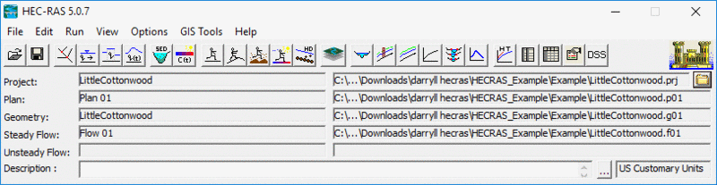
Selecting the Project button calls the
main HEC-RAS project screen, allowing for viewing and editing.
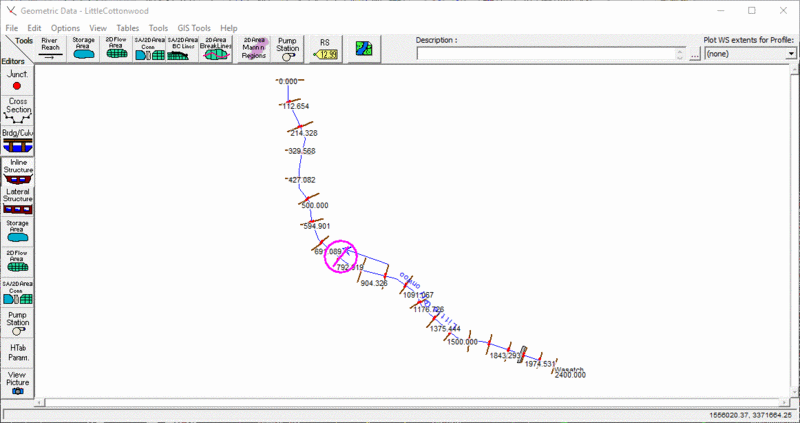
Selecting the Geometry button calls the
HEC-RAS Geometric Data dialog, with tools and editors to add
complexity to the reach.
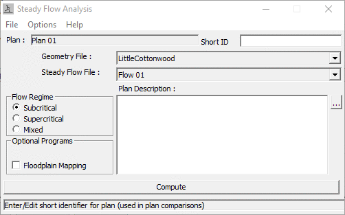
Selecting the Steady Flow Analysis button
calls the HEC-RAS Steady Flow Analysis dialog. Type a Short
ID if desired. Choose a Flow Regime. Choose Optional
Floodplain Mapping if desired. Input a Plan Description if
desired. Click the Compute button to analyze the
steady state flow input when the HEC-RAS project was created.
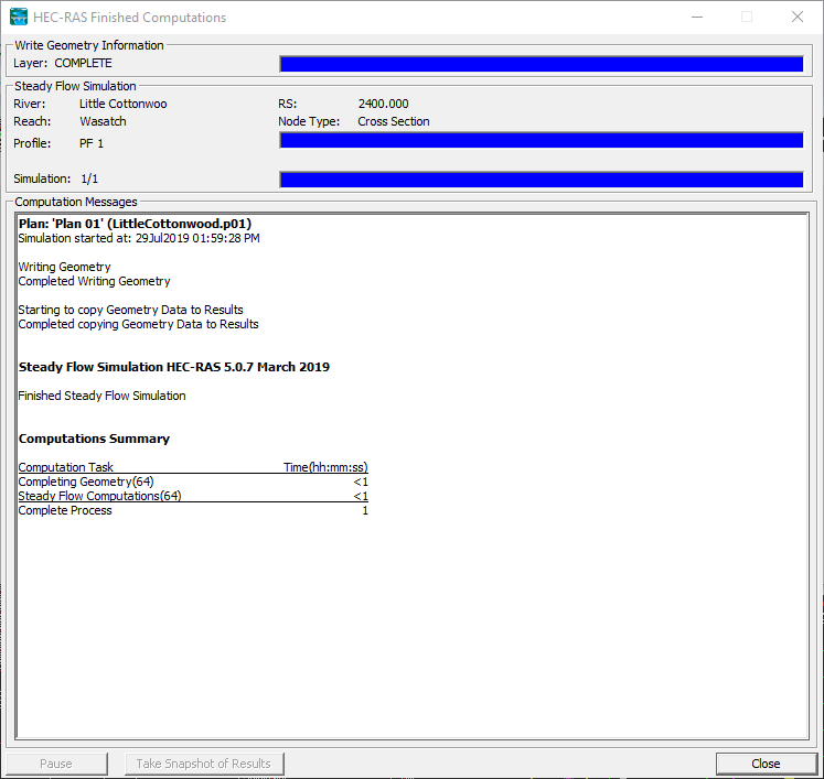
Once the computations are completed, the HEC-RAS
Finished Computations dialog is displayed or errors are listed.
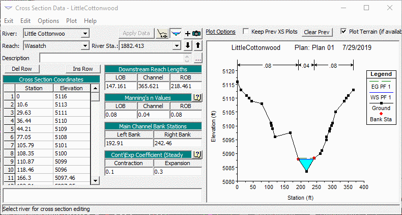
Returning to the HEC-RAS Manager, clicking the
X-Section Tab, selecting a Station and clicking Edit
calls the HEC-RAS Cross Section Data dialog. Examine the
Steady Flow at any station by clicking the Up and Down
arrows
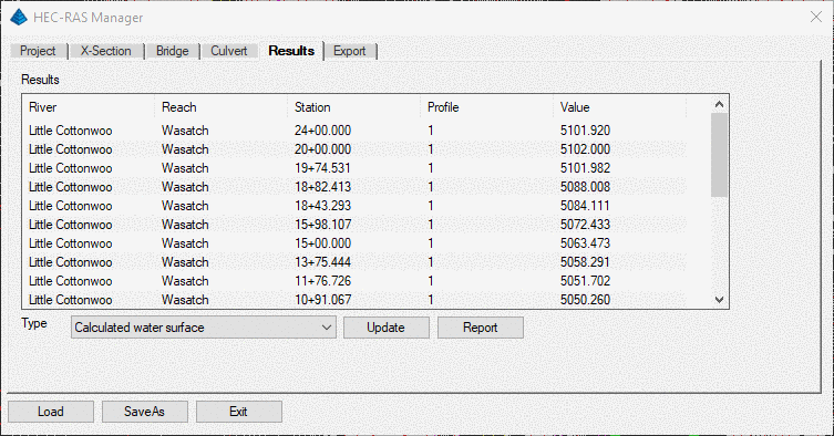
Use the HEC-RAS Bridge and Culvert Tabs to
add bridges and culverts along the reach. You will need to
re-run the Steady Flow Analysis. Click the Results tab
on the HEC-RAS Manager. Select the Type of results desired
and click Update. The desired results are
displayed.
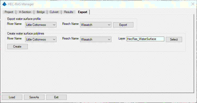
Once the desired results have been chosen and
updated, selecting the Export Tab in the HEC-RAS Manager
will allow the chosen results to be exported. In this case,
the results desired was Calculated water surface. From this
we can export a .pro file and/or create edge-of-water surface
polylines on a specified layer and automatically insert these into
the drawing.
Any changes or updates made during this
processing will not be saved to the HEC-RAS file system until
Save is clicked in the HEC-RAS Manager.
If you have built multiple Plans within HEC-RAS, use the Multiple Run button in the HEC-RAS Manager dialog to check or run multiple plans at once.
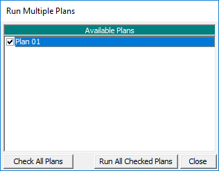
If you have built multiple Plans within HEC-RAS, use the Multiple Run button in the HEC-RAS Manager dialog to check or run multiple plans at once.
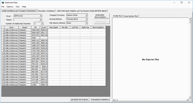
Clicking the Sediment Data button in the
HEC-RAS Manager calls the HEC-RAS Sediment Data dialog, used for
setting up and analyzing water sediment movement.
Pulldown Menu Location: Watershed
Keyboard Command: HECRAS
Prerequisite: HEC-RAS v. 5.0.0 or newer
Keyboard Command: HECRAS
Prerequisite: HEC-RAS v. 5.0.0 or newer