Draw Stage-Storage Curve
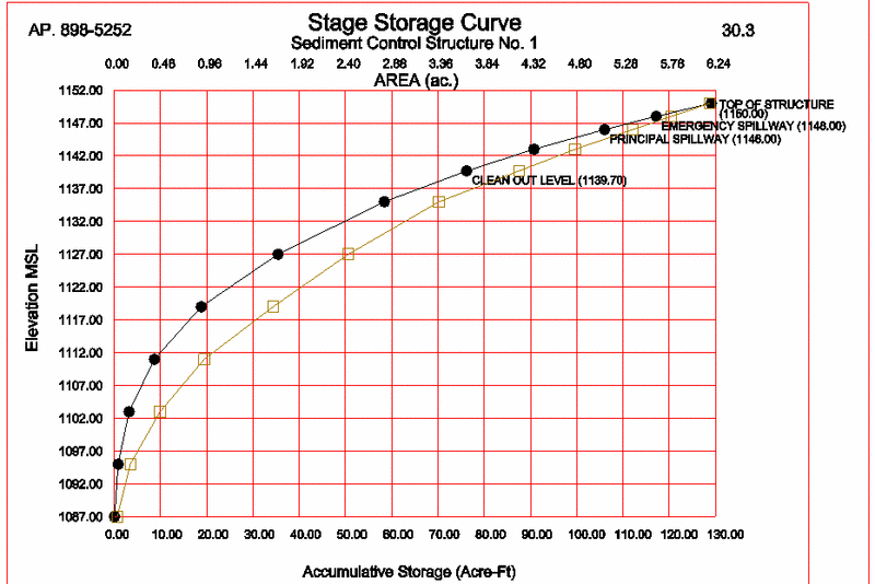
This routine draws a pond stage storage curve with pond elevation
on the vertical axis and acre-feet of storage on the horizontal
axis. It will plot and label the emergency spillway, principal
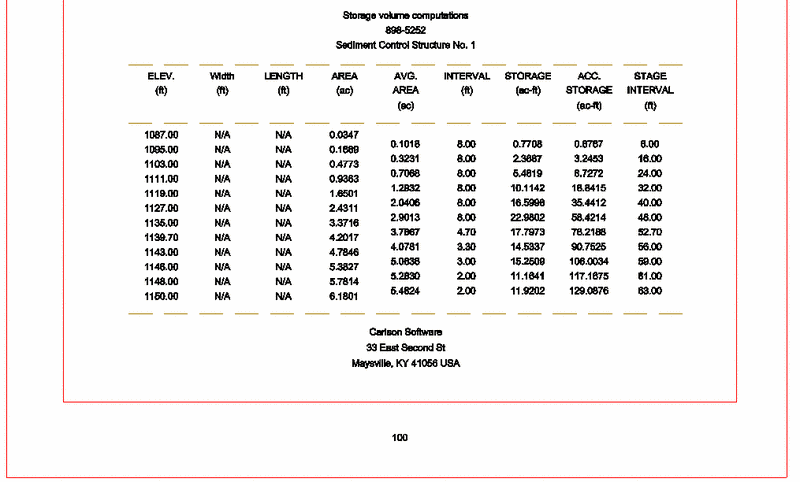
spillway and cleanout levels and will produce a table of storage
data. There is an option to plot the Stage-Area curve on the same
graph. The program will read a *.CAP capacity file of pond storage,
based on the surface area at each stage or elevation. CAP files
(short for "capacity") are made by Design Bench Pond, Design Valley
Pond, Rectangular Pond Design, Calculate Stage Storage and
Calculate Pond/Pit Volumes.
In addition to CAP file-based inputs, you can enter pond dimensions
directly by length-width, area at each stage, or volume at each
stage. If stage-storage curves are loaded from file, which contains
only volumes at different stages, then the width and length columns
are filled in as "N/A" (not applicable). Since volume-based
entry does not include area information, no CAP files are stored
with this option. However, the curves plot in all cases. Plots are
sized to fit on standard letter sized 8.5” x 11” sheets at the
selected scale for plotting. They are particularly suited for
permit applications, so the program will prompt for permit number
and page.
Prompts
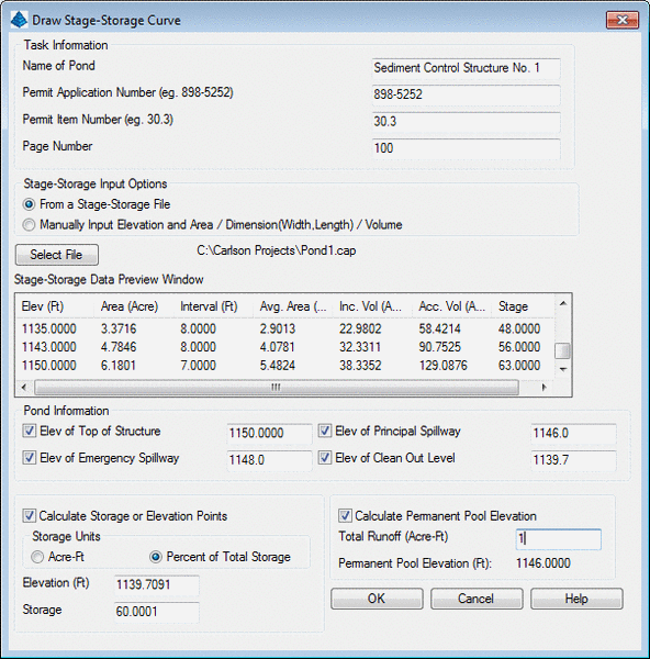
The program is dialog-driven. The first dialog controls file
loading and some pre-calculation options, and is shown below:
 Task
Information
Task
Information
This section allows for entry of the Name of the Pond, Permit
numbers and the page number. These fields will be labeled on the
final plot, ready to be inserted into a report.
Stage Storage Input Options
• From a Stage-Storage File: Using this
option, load the CAP file with the Select File button. This will
populate the preview window and fill in the top of structure
elevation. If the goal is to set the emergency spillway at an
elevation with storage at a certain acre-feet, enter the storage in
the lower left, hit the Enter key, and calculate the appropriate
elevation. A total runoff of the entered acre feet, subtracted from
the acre-feet at the principal spillway, will set the recommended
elevation of the "clean out level". If the pond silts up above that
level, then the silt needs to be removed. For example, the minimum
vertical separation between principal spillway and clean out level
is 1.5 feet in some regions. To compute permanent pool elevations,
enter the runoff quantities and hit the Enter key.
o Elev of Top Structure: This value is
entered automatically, read in from the CAP file.
o Elev of Emergency Spillway: Enter this
value either from the design, or from the Calculate Storage or
Elevation Points calculation.
o Elev of Principal Spillway: Enter this
value either from the design, or from the Calculate Storage or
Elevation Points calculation.
o Elev of Clean Out Level: This is a value
calculated usually by the Percent of Total Storage, or storage
below the principal spillway, such as 60% of storage capacity.
o Calculate Storage or Elevation Points:
Select the units to be entered, enter either the elevation or
storage, hit the Enter key to see the result.
o Calculate Permanent Pool Elevation:
Enter the total runoff and hit the Enter key to calculate the
permanent pool elevation.
• Manually input elevation and Area /
Dimension (Width, Length) / Volume : This option is used to
manually enter the pond area, dimensions or volume at increasing
stages (elevations), and all the options in the lower portion of
the dialog turn off and are not available, since the pond
characteristics are not yet known. Then prompting appears as shown
below:
Input (A)rea, Length/Width (D)imensions or <V>olume:
D
Stage No. 1
Elevation: 940
Width: 20
Length: 60
<Enter> for more, (R) to Revise, (E) to exit entry: If
you made a mistake, you could enter R and then enter a revised
Elevation, Width and Length. Otherwise, press Enter to
continue.
Stage No. 2
Elevation: 945
Width: 30
Length: 70
<Enter> for more, (R) to Revise, (E) to exit entry:
press Enter
Stage No. 3
Elevation <950.00>: The
program defaults to the last interval.
Width: 40
Length: 80
<Enter> for more, (R) to Revise, (E) to exit entry:
E to exit
A table appears, similar to the following:
Elev Width Length Area
Interval Avg. Area Inc. Vol Acc. Vol
Stage
(Ft) (Ft)
(Ft) (Acre)
(Ft) (Acre) (Acre
Ft) (Acre Ft)
-----------------------------------------------------------------------------
940 20.0
60.0 0.028
0.00
0.028 0.000
0.000 0.00
945 30.0 70.0
0.048 5.00
0.038 0.189
0.189 5.00
950 40.0 80.0
0.073 5.00
0.061 0.304
0.494 10.00
Areas are in acres. If the area method of entry were chosen
instead, the user would have been prompted for area at each
elevation (stage), and the summary table would be blank under the
width and length columns. Similarly, if entry was by volume
(in cubic feet), all width, length and area columns would be
blank.
Calculate Storage or Elevation Points (y/<n>):
y
Known (E)levation or known <S>torage:
Storage (e.g. 0.2 or %60 for 60% of total): %60
Storage: 0.30 Elevation: 946.759
Calculate Storage or Elevation Points (y/<n>):
press Enter. This allows you to move on. The advantage of
this option is the ability to find exact spillway and cleanout
levels by experimenting with needed storages or desired elevations.
For example, sediment cleanout levels are often set at 60% of total
storage, which would be in this case 946.76.
Elevation of Top of Structure: 950
Elevation of Emergency Spillway: 948.5
Elevation of Principal Spillway (Enter if same): press
Enter
Elevation of Cleanout Level: 946.76
Is Above Data OK (<y>/n): press Enter. 'n'
leads to re-entry of above 4 items
Regardless of whether the stage-storage information was
hand-entered or loaded from a CAP capacity file, both methods lead
to the next dialog, which defines the drawing and labeling of the
stage-storage/stage-area curve graph and text.
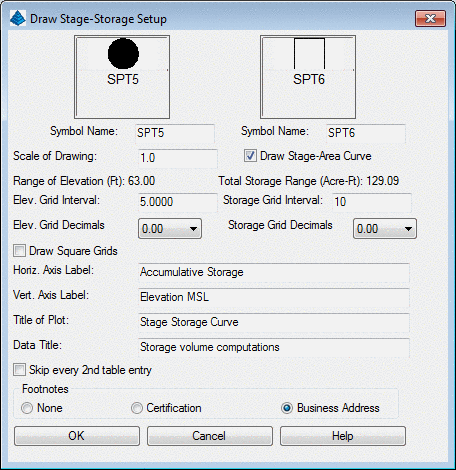 • Scale of Drawing: This sets the
size of the plot for CAD. A scale of 1.0, will draw the page 8.5 x
11 drawing units in the CAD window.
• Scale of Drawing: This sets the
size of the plot for CAD. A scale of 1.0, will draw the page 8.5 x
11 drawing units in the CAD window.
• Elev. Grid Interval: This sets the
interval of the horizontal grid lines.
• Elev. Grid Decimals: Controls the number
of decimals in the elevations.
• Storage Grid Interval: This sets the
interval of the vertical grid lines.
• Storage Grid Decimals: Controls the
number of decimals in the storage and area.
• Draw Square Grids: This setting sets the
grid lines to even squares instead of rectangles. It can change the
aspect ratio of the graph and may not always fit properly.
• Axis Labels and Titles: These are custom
entered names that will appear on the graph.
• Skip every 2nd table entry: It is often
beneficial to skip every other row, since the text rows may exceed
the space allotted to the table.
• Footnotes:
o None
o Certification: The default is a KY
certification that will read: I----, REG.-----,DATE-----hereby
certify in accordance with 405 KAR 7:040E, Section 103 that this
document is correct as determined by accepted engineering practices
and includes all the information required of it by KRS Chapter 50
and KAR Title 405.
o Business Address: This option will
prompt for the company name and three lines of addresses, as shown
below.
Pick Starting Position: pick lower left corner of stage
storage curve on screen
Company Name: Carlson Software
Address Line 1: 33 East 2nd Street
Address Line 2: Maysville, KY 41056
Address Line 3: Enter
Store Pond Capacity File (y/<n>): y. This
prompt appears if you hand-enter stage-storage information within
the routine and is followed by the normal save file dialog.
Note that if Drawing Setup is set to metric, the stage-storage
curve is calculated in cubic meters and all entries are in meters.
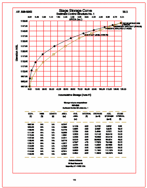
The final result of a typical combined Stage-Storage and Stage-Area
plot is shown below:
Pulldown Menu Locations:
Structure in Hydrology, Surface in Mining
Keyboard Command: stage
Prerequisite: None