This command sets the drawing format for sewer
pipeline and inlet/manhole annotations drawn for the sewer network.
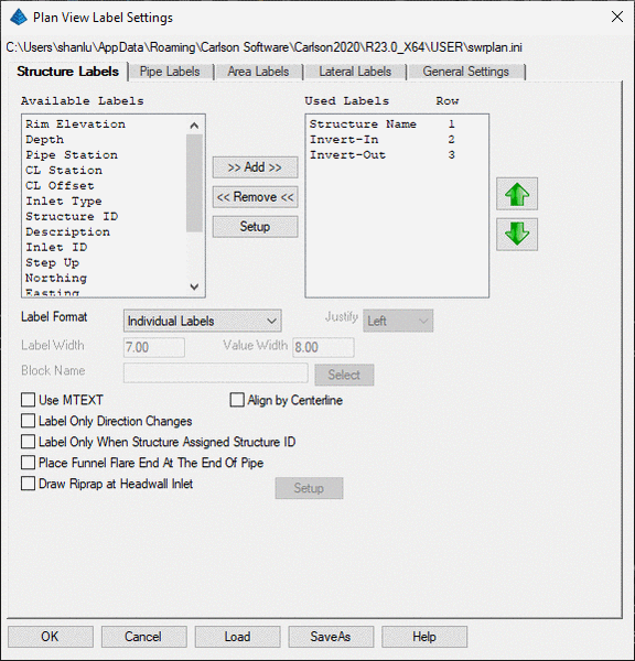
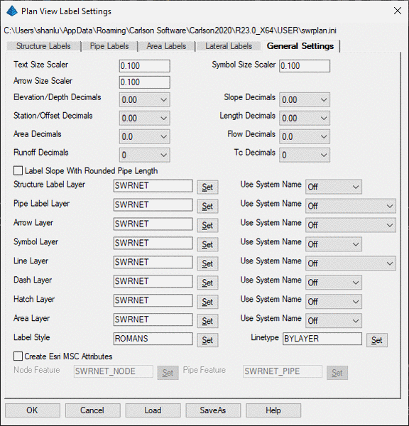
The settings are entered in a dialog with tabs for Structure
Labels, Pipe Labels and General Settings. Shown below is the
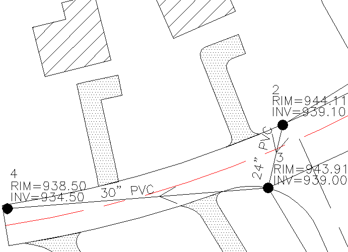
manhole or inlet name, along with rim elevation, invert elevation
and the labeling of the sewer pipe itself. When the network
entities are selected by the 3D Viewer Window command, they are
automatically converted into 3D entities.
Under Structure Labels, you can choose whether to
label the structure name, structure description, northing, easting,
rim elevation, depth, pipe station, CL station, CL offset, inlet
type, invert-in elevation, invert-out elevation, structure ID,
Inlet ID or custom offsets. The custom offsets label elevations
relative to either the structure rim elevation or invert elevation
with a specified offset. The list of available fields is on the
left and the list of fields to label is on the right. The order of
the fields in the right side list is the order of the labels in the
drawing. Use the Add, Remove and Up/Down arrow buttons to move
fields between the lists and change their order. To edit the
parameters for a field, highlight the field name on the right list
and pick Setup. You can set the label prefix and suffix and whether
to start a new row. If new row is off, then the field will be put
on the same row as the previous field in the list. The pipe station
is the accumulative length of the pipes from the outfall up to the
structure. The CL station and offset values are calculated from the
reference CL that is assigned to the structures in the sewer
network. The invert elevations can be positioned either above the
structure or along the associated pipe direction. For Inverts, the
Add Quadrant option adds the bearing quadrant of the associated
pipe direction to the invert label prefix. The options for Label
Format are Individual Labels, Data Table and Attribute Block. For
Individual Labels, the program draws regular text entities. The Use
MText option will draw the labels as MTEXT entities. Otherwise they
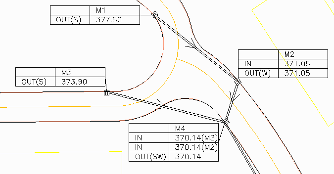
are drawn as TEXT entities. The Data Table method will put the
labels is a block as shown below. There are settings for the size
of the block columns and the block label justification. The
Attribute Block method inserts a block and puts the labels into the
block attributes. The Align By Centerline option will rotate the
labels to be parallel with the pipe. Otherwise the labels are drawn
horizontal to the current twist screen. The Locate Only Direction
Changes will only label when the pipes to the structure have a
deflection angle. This setting applies to utility networks that
have a lot of nodes in straight lines and you only want to label
the end nodes. The Label Only When Structure Assigned Structure ID
option will only draw the structure labels when the structure has
an ID other than None. This option is meant for clearing up
unnecessary labels for cases like utility networks that have a lot
of structures without ID's. The Place Funnel Flare End At The End
Of The Pipe relocates the funnel to be part of the pipe length. The
Draw Riprap At Headwall Inlet draws a hatch pattern using the
pattern and size set under Setup.
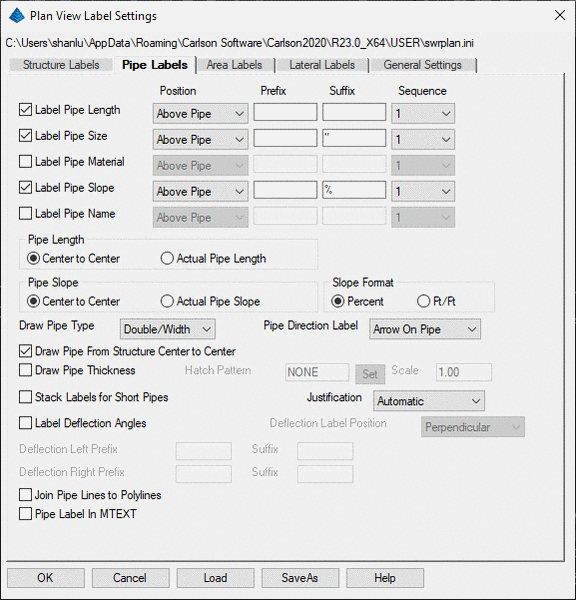
Under Pipe Labels, you can choose whether to label the pipe size,
material, length, name or slope. For each label, there are settings
for the prefix and suffix, for whether to put the label above or
below the pipeline, and controls for label sequence of the fields.
For length and slope, the labels can be based on structure
center-to-center or actual pipe dimension that removes the width of
the structure and goes from the structure edges. The Pipe Direction
Label has two styles for flow direction arrows. The Draw Line Type
sets the method for drawing the pipelines as 2D polylines, 3D
polylines or parallel 2D polylines set apart with the width of the
pipe. The pipe is drawn at outside border of the symbols, however
the Draw Pipe From Structure Center to Center will draw pipes from
structure center to center. The Draw Pipe Thickness will show the
thickness of the pipe with the option to hatch. The Stack Labels
For Short Pipes option will automatically make a stacked row of
labels when the pipe segment is too short to fit on a single row.
The Deflection Angle options have separate prefix/suffix settings
for left and right, and the label rotation can be horizontal to the
current screen view or perpendicular or parallel to the pipe. Pipe
Label in MTEXT allows the user to label pipe runs using MTEXT.
.
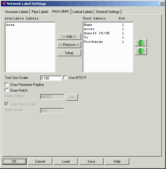
For Area Settings, the program can label the
drainage parameters for each inlet including area, runoff
coefficient, Tc and discharge. There is also the ability to draw a
perimeter polyline for the drainage area and to hatch the
area.
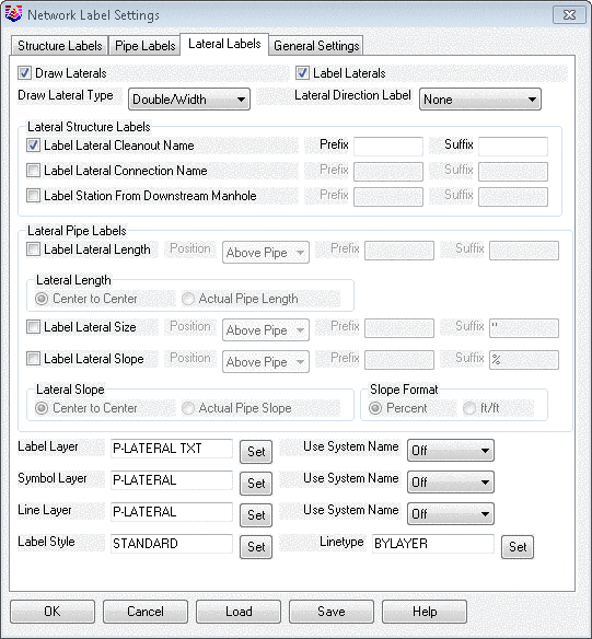
For Lateral Settings, you can choose whether to Draw Laterals and
Label Laterals. The Draw Lateral Type allows the user to select 2D
Polyline, 3D Polyline, Double/Width, or Dashed/Width. Lateral
Direction Label has three styles None, Parallel Leader, or Arrow On
Pipe to show the direction of flow along the lateral. For the
Lateral Structure Labels the user can specify a Prefix or Suffix
for the Label Cleanout Name, Label Lateral Connection Name, and
Label Station From Downstream Manhole by placing a check box with
these two options if you choose to label. The check box toggle for
Label Lateral Length the user can control the position of either
Above Pipe or Below Pipe and also add a Prefix or Suffix. For
Lateral Length the labels can be based on structure
center-to-center or actual pipe dimension that removes the width of
the structure and goes from the structure edges, and also specify
what is to be labeled with a position, Prefix, or Suffix. The
Lateral Slope the labels can be based on structure center-to-center
or actual pipe slope, and toggle between the Slope Format of
Percent or ft/ft. Layers can be assigned for the Labels, Symbols,
and Linework and also the System Name as either Off, Prefix, or
Suffix. Use the Label Style to assign text standard and set the
Linetype.
You are free to move the text anywhere desired for better appearance after it plots. The labeling will change automatically on the drawing if any of the sewer network information is edited or if the label settings are changed. This automatic redraw will put the labels back in their original positions if you moved the labels with standard drafting edit tools. If the Move Sewer Label command is used, the labels will stay at their modified position even after the automatic redraw. The labeling and manhole itself will be removed from the screen by the command Remove Sewer Structure, along with connecting pipe sizes and invert elevations of the immediate upstream and downstream manholes. The command Draw Sewer Network--Plan View will also redraw and label the sewer network that is "set" and current, according to the annotation parameters of this command.
Pulldown Menu Location: Network
Keyboard Command: swrsetup
Prerequisite: None