Block Model 3D Viewer
This command allows you to view a block model in
the 3D viewer window directly from the .blk file. When the command
is executed, you will be prompted to select a .blk file and a grade
parameter file (.gpf file - controls coloring of the blocks). After
selecting these files, the below dialog will appear.
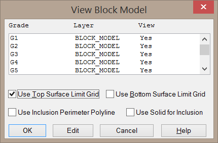
Use Top/Bottom Surface Limit Grid: These toggles allow you
select constraining elevation grids. Any blocks with a centroid
above/below these elevation grids will not be drawn in the 3D
Viewer.
Use Inclusion Perimeter Polyline: When enabled, you will be
prompted to select an inclusion polyline. Any blocks with a
centroid outside this polyline will not be drawn in the 3D
Viewer.
Use Solid for Inclusion: When enabled, you will be prompted
to select a solid (.mdl file). Only blocks with centroids inside of
this solid will be drawn.
Edit: This button will allow you to customize the properties
of the selected grade. When clicked, the below dialog will appear.
You may also open this dialog by double-clicking a grade name.

Draw Grade: When enabled, the selected grade
category will be drawn in the 3D Viewer.
Layer Name: This field sets the layer name for the blocks.
You may select an existing layer by clicking the Set
button.
Color: This button allows you to select a new color for the
blocks within the selected grade.
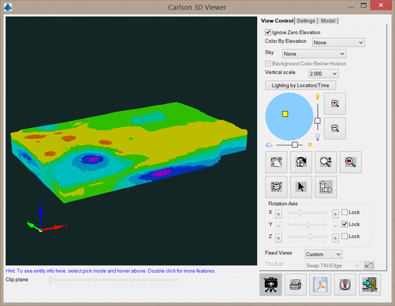
After selecting these settings and clicking OK, the
3D Viewer window will be displayed as shown below. All controls for
this dialog are discussed in the 3D
Viewer Window section of the help manual.
You may change the coloring of the blocks by right-clicking "Block
Model" on the Model tab. The below dialog will be displayed.
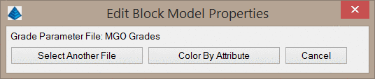
Select Another File: This option will prompt you to select a
new Grade Parameter File to recolor the block model.
Color by Attribute: This option will allow you to recolor
the blocks by defining the attribute values and colors on-the-fly.
This is a simplified version of a Grade Parameter File, with the
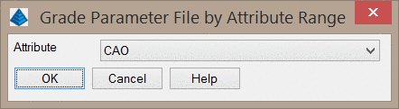
restriction that coloring can only be based on a single attribute.
Clicking this option will display the below dialog, which will
prompt you to select the attribute of interest.
The next dialog that appears is shown below. Here you can define
the range of values and the color for that range.
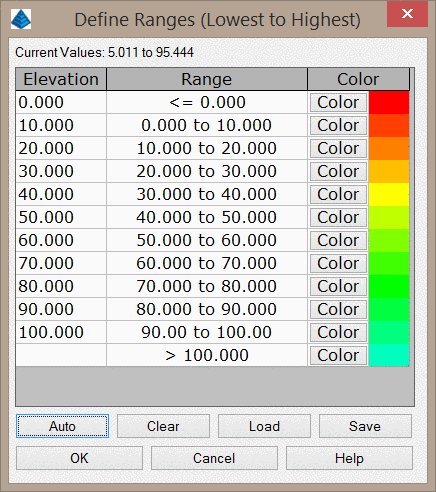
The Auto button can be used to quickly create the ranges
using a constant interval. This dialog is shown below.
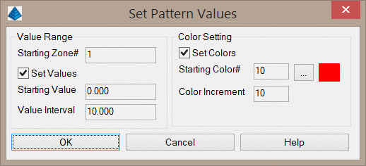
Starting Zone: This value sets the first row to modify. If
several rows have already been defined and do not need to be
modified, set this value to the next undefined row.
Set Values: This option will modify the values of the rows.
If the values have already been set and do not need to be changed,
this option should be disabled. When enabled, the Starting Row
value will be set to the Starting Value. Each row after will
increment by the Value Increment.
Set Colors: This option will modify the colors of the rows.
If the colors have already been set and do not need to be changed,
this option should be disabled. When enabled, the Starting Row
color will be set to the Starting Color #. Each row after
will increment by the Color Increment. The color values may
be viewed by clicking the ellipse button to the right of the
Starting Color.
Pulldown Menu Location:
Block Model
Keyboard Command:
blkm_cube
Prerequisite: A BLK model
file and a GPF grade parameter file.