This function allows you to modify the properties of multiple
point attributes at the same time. This command gives you complete
control over the Carlson point attributes that are present in the
drawing. Changes can be made to each attribute -- the point number,
elevation, description or symbol -- all in one motion. For example,
you could rotate the elevation text of some points to 45 degrees,
change the height of the description text for all the points in the
drawing, or change the layer for a particular attribute. Once this
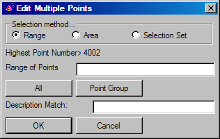
command is chosen, the entry Edit Multiple Points dialog, a smaller
box, appears. Here you can determine your point selection method.
There is also an option for description matching.
After the selection of the points to change, click OK, and the subsequent, larger Edit Multiple Points dialog boxes will appear. The number of points selected will be shown at the top of the dialog boxes.
Edit Multiple Points dialog
For each attribute, you can change any number of the
properties, including the layer, height and rotation. These dialogs
will reflect the current status of each attributes properties. If,
for example, you select 10 points, and 5 of them have the elevation
rotation set at 45 degrees, and the other 5 are set at 0 (zero)
degrees, then the rotation edit field will say *varies* to let you
know that the properties of the points you selected are not the
same. Here is an example of the dialog box.
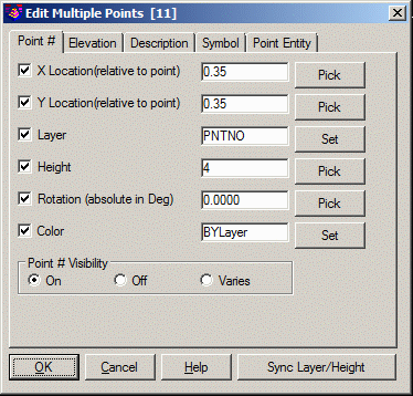
The X location refers to the distance in the X direction from the center (or insertion point) of the point symbol. The Y location refers to the distance in the Y direction from the center (or insertion point) of the point symbol.
The Layer refers to the
layer of the individual attribute, not the entire attribute block.
To change the layer of the entire attribute block, use the
Attribute Block Layer
option. The Height is
expressed in real units (generally feet or meters), not plotted
size. The Rotation angle is
expressed in absolute decimal degrees. The Color can be set ByLayer or to a
specific color. The Point Entity
Layer refers to the layer that the node of the point
resides. The required layers can either be typed in manually, or
the Select button can be used to pick from the existing layers in
the drawing. If a new layer is desired, simply type in the name of
the new layer and it will be created automatically. Use the layer
property manager to edit the properties of this new layer, if
required. The Visibility
setting allows for attributes to be shown or hidden in the
drawing.
To change a point symbol, check on the Symbol tab and use the select button to
choose the desired symbol. On the Point Entity tab, the
Attribute Layout ID refers
to the attribute layout style defined in Point Defaults or Field to
Finish code definitions. This option allows you to change the
particular layout with one of the other available styles or to a
customized style if defined. The Pick buttons allow you to pick two
points to define a distance (or angle in the case of Rotation). If
you want to select a line to define a distance or angle, select two
points on the line with the appropriate OSNAP.
Select the attribute to edit, make the necessary changes to this
attribute and then move on to the next attribute if required.
Changes made to the attributes are remember individually, which
allows for switching back and forth though the attributes until the
command is completed. After completion the new settings for the
point attributes will be retained until changed or redrawn on the
screen.
The Sync Layer/Height
function sets the layer or height for some or all the attributes.
The layer and height can be entered manually or pick an existing
attribute to get the value. The Save and Load
functions are a way to store and recall all the point display
settings to a .PT file for having different point styles to reuse
or share.
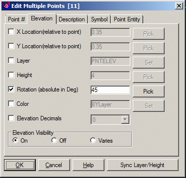
Example sequential use of Edit Multiple Points dialog
Again, the number of points selected will be shown in the dialog title. Let's now define the changes for each attribute individually. In the following example, suppose we want to rotate the elevation text to a 45 degree angle, move the description to the right and change the symbol. First, click on the Elevation for the Attribute to Edit. Now, select the Rotation option and type in 45. The dialog box should be as below.
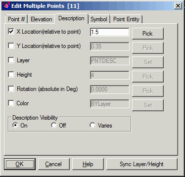
Now, select the Description option for the Attribute to Edit.
Select the X location from the Items to Change. Enter 1.50 in the
box. This value makes the description line up better with the
rotated elevation. The dialog should be as below:
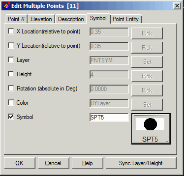
Now, for the final change, select the Symbol for the Attribute
to Edit. We want to actually change the point symbol. To do this,
toggle on the option to change the symbol by clicking in the box
beside the word Symbol. Next, press the Select button and select
symbol SPT5. The dialog should be as below:
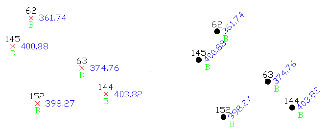
At this point we are ready to select the OK button to perform the changes. The following image shows the points before and after the changes.
|
| Before and After Changes |
Pulldown Menu Location: Points
Keyboard Command: modpnts
Prerequisite: Points drawn on the screen