This command reports the cut or fill between your current
position and a design surface. The design surface can be one flat
elevation, a grid file, a triangulation file, a road design file,
or a section file.
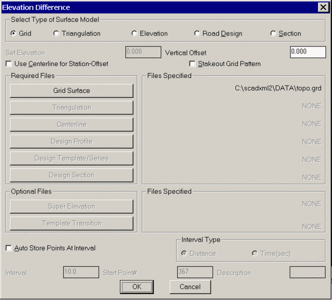
The type of design surface is set in the dialog shown. The Vertical Offset in this dialog can be used to modify the design surface by adding this value to the design surface. For example, if you have a design surface for the top of a road and you want to get cut/fill values to a 1.5 subgrade, then enter -1.5 in the Vertical Offset field. The Use Centerline For Station-Offset option will report the station-offset of your current position in addition to the cut/fill. When this option is active, the program will prompt you for the centerline file (.CL) to reference. For GPS and robotic total stations, the Auto Store Points At Interval will creates points whenever your position moves by more than the specified distance or time interval. This option is similar to the Auto Points At Interval command with the addition that the default description will include to cut/fill to the design surface. When all the options are set, pick OK and the program will then prompt you for a grid file or triangulation file if you have selected these types of design surface.
Elevation Difference with GPS
Carlson Field will continually read your current position from
the GPS receiver. A dialog box appears displaying your current
position. Carlson Field finds the design elevation for this point
and compares it to the elevation being reported by the GPS
receiver. It then tells you how much cut or fill is required to
reach the design elevation from your current position. An arrow
icon will appear on the drawing showing your location. You can move
around the site while in Elevation Difference mode and
Carlson Field will report the necessary cut or fill in real-time.
If you move off the area covered by the design surface, then the
program will stop reporting cut/fill and instead will report "Off
Surface". When using a grid or triangulation surface, the bottom of
the dialog shows a profile of the surface in real-time in the
direction of your movement.
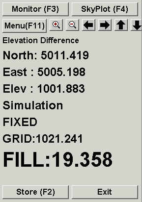
The Store button will create a point at the current position. The default description will include the current cut/fill. When Store is selected, a dialog box will appear for entering the point number and description.
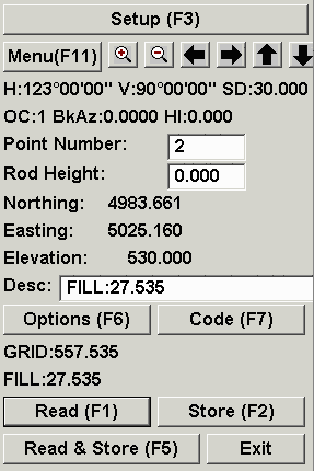
Elevation Difference with Total Stations
Elevation Difference uses a dialog box that is very similar to the Point Store dialog. Under the Setup button, make sure that the occupied point, backsight and instrument height are set. Then have your rodman set the prism over the point you are interested in. Pick Read(F1) or Read & Store(F5) and the total station will take a shot.
After the shot is taken, the dialog box looks like the one at right. Carlson Field found the design elevation for this point (557.535) and compared it to the actual current elevation (530.0). Based on the current and design elevations, Carlson Field reports to how much cut or fill is required to get to design elevation. In this case, it is fill 27.535. The cut/fill also appears in the Desc box. If you click Store, Carlson Field will record this point and plot it on the drawing, including the Desc as a label.