This function stakeouts a point at a given station and offset of
a centerline and reports the cut or fill to a design elevation. The
centerline and design elevation can be defined by four methods as
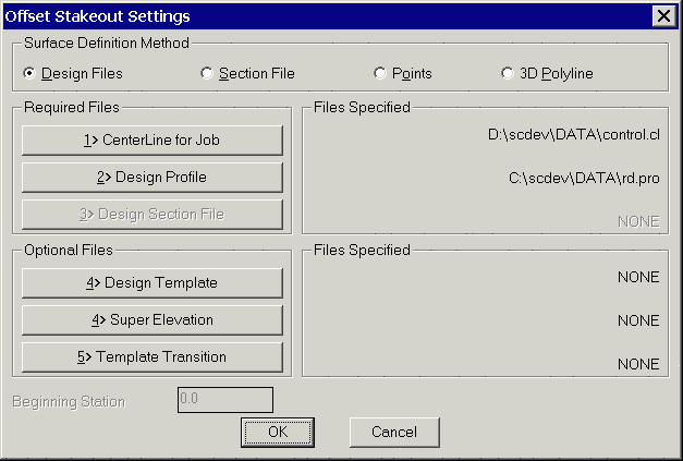
set in the dialog show. The Design Files method uses a centerline
file (.CL) for the horizontal alignment and a profile file (.PRO)
for the vertical alignment. A template file (.TPL) for the design
cross section is optional for the cross slope. Without a template
file, the program will use the elevation of the profile along the
centerline. A superelevation file (.SUP) and a template transition
file are optional. These design files can be created with the
routines in the Roads menu. The Section File method uses a
centerline file for the horizontal alignment and a section file
(.SCT) for the design elevation. The section file consists of cross
sections of offset/elevation points for a series of stations.
Section files can be used instead of the Design Files method when a
road design is too complicated to model using design files. For
example, if the road contains special ditches at various offsets
and varying lane widths, then it may be easier to enter a final
section file than to define the template and template transitions.
The Points method uses two points to define both the horizontal
alignment and design elevations. The design elevation is linearly
interpolated between the points. The points to used are specified
in the next dialog by entering point numbers from the current
coordinate file or by directly entering the coordinates. The 3D
Polyline method uses a 3D polyline for both the horizontal and
vertical alignment. With this method, the program will prompt you
to select the 3D polyline from the drawing. For both the Points and
3D Polyline methods, you can specify the starting station of the
horizontal alignment. When using the Design Files and Section File
methods, the horizontal alignment starting station comes from the
centerline file.
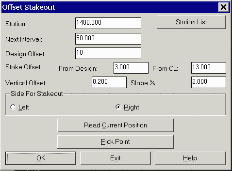
After specifying the offset stakeout method, Carlson Field prompts
for the station and offset to stakeout as shown in the dialog. The
station should be entered as a number without the "+" symbol. The
Next Interval field is used to increment the stakeout station for
the next stakeout point. In addition to incrementing to the next
interval, Carlson Field will also pick up special profile or
centerline points between intervals. Centerline special points
include: start point, end point, curve (PC, PT) and spiral (TS, SC,
CS, ST). Profile special points include: start, end, vertical curve
(VC, VT), high points and low points. For example, if the current
station is 100 and the interval is 50 and there is a centerline PC
at 112.4, then the next station after 100 will be 112.5 followed by
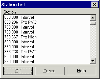
150. The Station List button brings up a list of all the station
intervals and special stations. You can select a station to
stakeout by selecting the station from the list and pressing
OK.
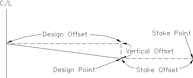
There are two offsets to allow for separate offsets for the design elevation and stake location. The Side For Stakeout toggle selects between left and right offsets. The Design Offset is where the stake point elevation is calculated. The Stake Offset determines X,Y position of the stakeout point by finding this offset at the stakeout station along the horizontal alignment. Having Design and Stake offsets applies, for example, to staking the back of a curb, where the Design Offset is 12, but the stake offset is 17 (5' behind the back of curb, with the elevation reference to the actual back of curb design elevation). The Stake Offset can be specified either as an offset from the design point or as an offset from the centerline. There is also an optional vertical offset that applies to the elevation of the design point. With the Design Files and Section File methods, the vertical offset works as an offset from the template or cross section surface. For example, a vertical offset of -0.5 could be used to stakeout the bottom of a 0.5 subgrade. With the 3D Polyline and Points methods, the vertical offset adjusts the elevation from the along the centerline at the stakeout station.
The Read Current Position button will take a measurement from
the GPS or total station to find the station of your current
position. This current station is put in the Station field.
The Pick Point button will prompt you to pick a point in the drawing view. The station and offset of this point are used to fill out the Station and Offset fields.
After specifying the stakeout stations and offsets, Carlson Field uses the same stakeout function as used in the Stakeout command. This stakeout function guides you to the stakeout point and reports the cut/fill to the design elevation. You can store the stakeout point. When the stakeout is done, the station/offset dialog appears for staking the next point. Either enter the next station/offset or pick Exit to end Template Stakeout.
For total stations, you should run the Equipment Setup command before Template Stakeout to set the occupied point, backsight and instrument height.
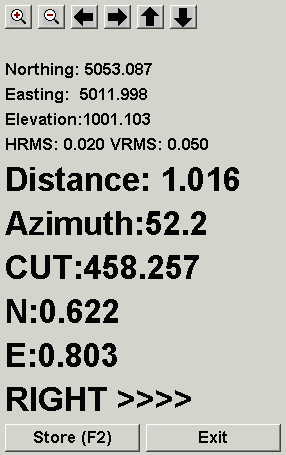
|
| Stakeout dialog for GPS |
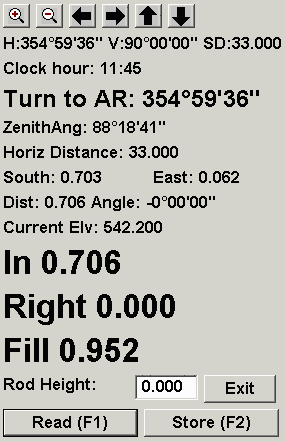
|
| Stakeout dialog for total stations |
Pulldown Menu Location: Roads
Prerequisite: None