|
|
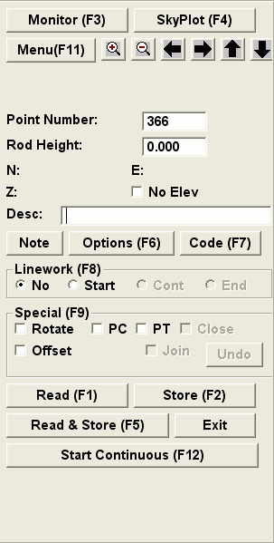
| Point Store dialog for
GPS |
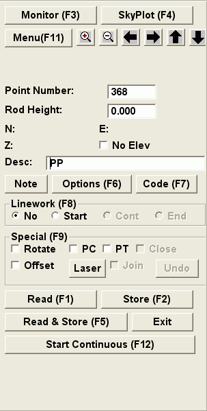
Point Store dialog for GPS with a
Laser |
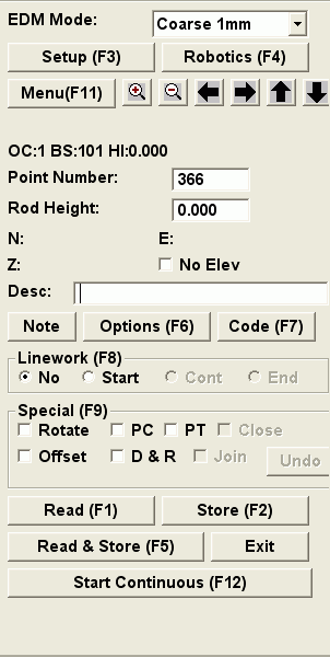
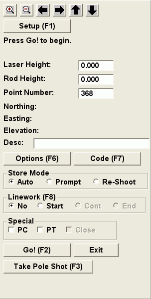
This function creates points by reading from GPS or total station equipment. The new points are stored in the current coordinate and simultaneously drawn in the drawing. The measurement data is also stored to the current raw file which has the same name as the coordinate file except with a .RW5 instead of .CRD file extension.
The Point Store dialog docks on the side of the drawing window. This allows you to see the drawing view as you collect points. You can use the arrow keys to pan the drawing and the Page Up/Page Down keys to zoom out and in. There are also icons for the pan and zoom functions at the top of the dialog. Also, besides clicking the function buttons, most buttons have an associated function key such as F1 that you can use to run the routine.
Before taking measurements, make sure that the rod height is correct.
To take a measurement from the survey equipment, pick the
Read button. The calculated northing, easting and elevation
will be displayed in the dialog and a temporary icon will be shown
in the drawing at the point location.
|
|
|
| Point Store dialog for
GPS |
Point Store dialog for GPS with a
Laser |
|
|
| Point Store dialog for non-robotic total station | Point Store dialog for robotic
total station |
Before storing the point, make sure that the point number and description are set in the Point Number and Description fields. The point number is a required field for storing to the current coordinate file. If the point number specified already exists in the coordinate file, then a dialog will pop-up with options to overwrite the existing point number, to use another point number or to cancel storing the new point. The Point Number field will automatically increment after storing the point.
The Description is an optional field for identifying the point. The maximum length of the description is 32 characters. Besides naming the point, the description can also be used to with Field-To-Finish to draw linework and to determine the symbol of the point in the drawing. When the Field-To-Finish option is set on in Options, the program will lookup the description in the current code table. If the description matches one of the codes, then the code can determine the symbol, layer, format of the point when it is drawn. Otherwise the defaults in the Point Setting section of the Options dialog are used for the point symbol, layer and format.
To store the new point to the coordinate file and draw the point, pick the Store button. At the time that Store is applied, the program uses the point number, description, linework options and special options currently set in the dialog.
You can also use the Read & Store button to do both functions in one step. With this method, the program will take a measurement and if the measurement is successful, then the point will be stored immediately.
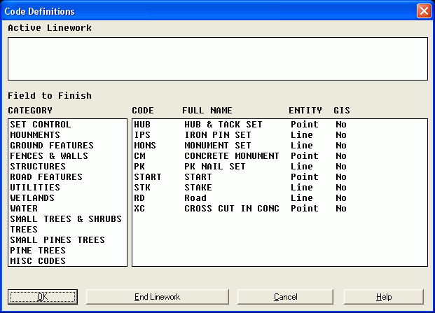
The Code button brings up a list of point descriptions from the current Field-To-Finish code table. You can select a code from the list to set this code as the current point description. This function also shows a list of all the descriptions of currently active linework. You can end a currently active linework by highlighting the linework description from the Active Linework list and pressing the End Linework button.
Many of the options for storing points can be set in the Configure Field>Point Settings command. The Options button in this dialog is a shortcut to these point settings.
If you want lines or polylines to connect the points that you are about to record, select the Start button under Linework. After the first point, the Linework selection will change itself to Cont meaning continue. Leave this selected while you are recording points in the same line. Before shooting the last point in your line, change it to End. If you want the line to close itself onto its first point, check the Close button.
The Field-To-Finish Linework option is an automatic way to start
linework. The program will lookup the point description in the code
table. If the description matches a code and the code is defined to
create linework, then the Start toggle in the
Linework options is turned on. Otherwise you can begin new
linework by toggling on Start manually.
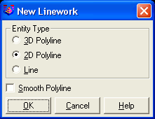
When a point is stored and Start is on, Carlson Field pops-up a dialog for choosing between a line, 2D polyline or 3D polyline. A 3D polyline can contain points with different elevations, but a 2D polyline always has an elevation of zero. The Smooth Polyline option will create Bezier smooth polyline through the points.
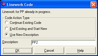
Carlson Field can keep track of several lines being drawn at once. Each line corresponds to a set of points with a different description. Let's say you are shooting a line of points called "fence" and you want to shoot some points on a curb, but you're not finished with the fence. You change the Desc box from "fence" to "curb". Carlson Field lets the fence line go for now. It changes the Linework selection to No. You want a line for your curb, so you select Start. The points you shoot now will form a new curb line. To go back to recording fence points, change the description back to "fence". The fence line you were working on will continue to include any new fence points you shoot. If you want to end this fence line, select End under Linework and Carlson Field will not connect any future "fence" points to this line. If you start a new linework with a description that already has linework, then Carlson Field pops-up a dialog with three options as shown. The Continue Existing Code option is the same as using Cont instead of Start. The End Existing and Start New option will end the active linework and start the new linework with the same description. The Use New Description option will keep the existing linework and start another linework with another description. For example if you are surveying two edge of pavement lines, you can have one with the description "EP" and the other with "EP2".
The PC and PT options are for drawing curves. If
you want to plot a curve, check the PC box before recording
the first point on your curve. Shoot as many points along the curve
as you need. Carlson Field can handle compound curves as well as
simple curves with this function. Before shooting the last point on
the curve, check the PT button. If you don't specify a PT,
Carlson Field will assume a three point curve.
Similar to Field-To-Finish linework, when looking up the point description in the code table, if the description matches a code and the code is defined to use data collection codes, then the Offset and/or Rotate toggles in the Special options are turned on. Otherwise you can create an offset and symbol rotation by toggling them on manually. Offset is for defining a left/right offset or an azimuth based offset. It also has the option for a vertical offset. Rotate will control the rotation angle of the symbol that is drawn when the point is stored; if enabled, the drawn symbol will be rotated based on the current heading of movement.
The Undo button will remove the last point number created. The point is removed from both the coordinate file and the drawing.
For GPS and tracking total stations, there is a Start Continuous button which makes Carlson Field continuously read from the instrument. The coordinates are displayed in the dialog and your position is shown with an arrow icon in the graphics view. To store a point, you can use the Store button without using the Read button first. Once continuous reading is active, the button changes to Stop Continuous which will put you back in standard reading mode.
Point Store with GPS
When using GPS equipment, Carlson Field will also report the RMS values and solution status when you take a reading. If Carlson Field gives you a message that your RMS values are too high when you try to read a point, you can click on the Monitor button to bring up the Monitor window which will give you information on how accurately your position is determined and how many satellites you are tracking. The Skyplot button will bring up the window showing you where in the sky the satellites are.
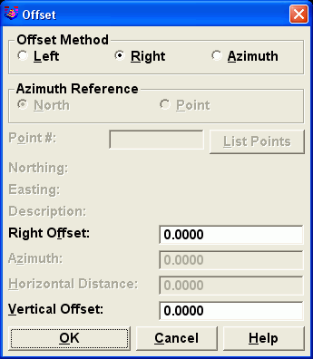
For points that are hard to reach directly by GPS, you can use
the Offset option. This option can be used in areas of
limited satellite communication such as high walls or under a tree.
This allows you to setup the rover in a clear area and read the
coordinate. The point that is actually stored is offset from the
rover position. To create an offset point, turn on the
Offset toggle and then choose Read. The offset
direction can be entered as left, right or azimuth. The left and
right offset is relative to the rover position at the previous
read. The offset distance is entered in the dialog. A Vertical
Offset can also be specified. Choose Store to store this
point after the offset is done.
 Offsets can also be done with laser
guns when the laser option is setup in Configure Field>GPS
Settings. There are two methods for taking laser offsets. One
method is to use the Offset toggle and the Read
button. In the Offset dialog, there is button for Read Laser for
using the laser measurement for the offset distance and/or angle.
This method creates a single offset point.
Offsets can also be done with laser
guns when the laser option is setup in Configure Field>GPS
Settings. There are two methods for taking laser offsets. One
method is to use the Offset toggle and the Read
button. In the Offset dialog, there is button for Read Laser for
using the laser measurement for the offset distance and/or angle.
This method creates a single offset point.
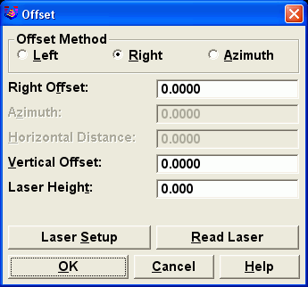
The other method is to use the Laser button which can
create many offset points. This method brings up another dialog.
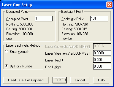
The Setup button can be used to set the Laser Alignment
Azimuth. This alignment applies to laser guns that use a
magnetic compass for the horizontal angle. The magnetic north can
vary from the north of your coordinate system. The Laser
Alignment Azimuth is added to the measured laser azimuth to
adjust for the difference. To set the alignment azimuth, specify a
reference backsight direction by either entering an azimuth or by
point number. Then choose the Read Laser For Alignment
button and take a laser shot towards the backsight. The program
will compare the azimuth from the laser with the reference
backsight to figure the alignment azimuth. When the alignment
azimuth is set, pick the Go button. Carlson Field then
listens for measurements on the laser gun port. To take a shot,
sight the target point and press the laser trigger. Carlson Field
will read the laser measurement and read the GPS position. The
laser angle and distance are combined with the GPS position for the
new point coordinates. To return to regular GPS Point Store, choose
the Exit button.
Point Store with Total Stations
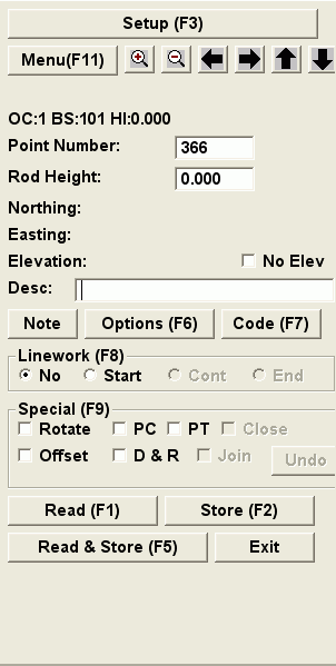
Before taking measurements with total stations, you need to specify the occupied point coordinates of the instrument, the backsight and the height of the instrument. This current setup data is shown in the "OC:# BK:# HI:#" line in the dialog. Also icons are draw to show the occupied point and backsight direction in the drawing view
The Setup button at the top of this dialog brings up the Total Station Setup dialog, where you can change your occupied point, backsight and instrument height.
For robotic total stations, there is also a Joystick button to turn the instrument, search for the prism and set tracking or standby mode.
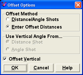
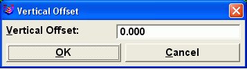
Carlson Field can shoot points with offsets. To shoot a point with an offset, check the Offset button on the Point Store dialog box. Click Read or press F1. A window appears to let you choose the type of offset to shoot. The choices are Distance/Angle and Enter Offset Distances. The Offset Vertical option will prompt for an elevation difference to apply to the point.
To do a Distance/Angle offset, you first take a distance shot
and then angle shot. For the distance measurement, have the rodman
stand to the side of the point. The prism and the point should both
be the same distance from the total station. Carlson Field takes
the first shot and gets the distance from it. It then prompts you
to read the angle. Turn the gun so that it is aimed at the point.
The prism is not needed for this step. Click OK and Carlson Field
reads the horizontal angle from the gun and combines this with the
distance from earlier to calculate the coordinates of the point.
Also for combining these shots, there is an option whether to use
the vertical angle from the distance or from the angle
shot.
With the Enter Offset Distances method, you can supply both a
left/right offset and an in/out offset. To do a In/Out offset, have
the rodman stand a measured distance in front of or behind the
point. The total station will take the shot and then Carlson Field
will ask you how to move the point: in or out and the distance. If
the prism is in front of the point, choose out. If it's behind the
point, choose in. To do a Left/Right offset, have the rodman stand
a measured distance to one side of the point. After taking the
shot, Carlson Field will ask whether to offset right or left. If
you are at the total station, looking at the prism, and the point
you are after is to the right of the prism as you're looking at
them, choose right offset. Otherwise, choose left offset.
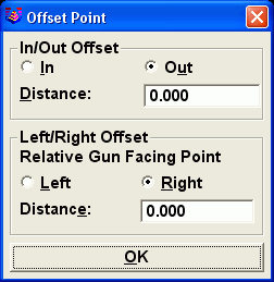
 Choose Store to store
this point after the offset is done.
Choose Store to store
this point after the offset is done.
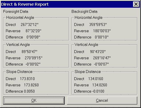
The D&R option stands for Direct and Reverse. When this box is checked, Carlson Field will take sets of four shots to determine the coordinates of the next point. Two shots are taken for both the backsight point and the foresight point: one direct shot, one shot with the total station reversed. This yields a more accurate reading. Two options are available for the order of shots when doing a D&R. The first is Backsight Direct, Backsight Reverse, Foresight Reverse, Foresight Direct. The other option is Backsight Direct, Foresight Direct, Foresight Reverse, Backsight Reverse. Carlson Field also offers the option of shooting multiple sets of Direct & Reverse for even greater accuracy. The Shoot Distances For Reverse Shots option determines whether to take distance measurements on the foresight reverse and backsight reverse shots. When this option is off, the program will still use the reverse shots to mean the angles. Otherwise the program will also use the reverse shots to mean the distances. The Use Robotics To Auto Flip Instrument option applies to robotic total stations to have the program automatically turn the instrument for reverse shots.
To shoot a point as a Direct & Reverse, check the
D&R box and click on Read. A dialog box appears,
offering the choice of orders for the shots. Before each shot,
Carlson Field tells you what kind of shot is being taken. After
each shot, Carlson Field reports the measurements and allows you to
confirm the measurement or to re-shoot. After all four shots are
taken, Carlson Field does the math and reports the accuracy of each
part of the measurement.
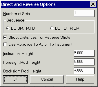
Choose Store after completing the Direct & Reverse to store this new point.