CG Options
The CG Options menu item
brings up the C&G Options
dialog, allowing you to view or change various CGSurvey
settings or save the currently configured settings to be used as
the default settings for a newly created drawings.
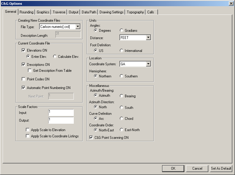
The C&G Options dialog
There are nine tabs on the C&G Options dialog. Each tab
pertains to a category of settings:
1. General tab - settings
regarding the coordinate file type for new files, units, scale
factors, and other general settings.
2. Rounding tab - number
rounding settings used for the print file and for text placed in
the drawing.
3. Graphics tab - specify
when CGSurvey draws points and lines, format of bearings and other
graphics related settings.
4. Traverse tab - settings
used by all traverse related features.
5. Output tab - specify the
name and layout of the print file and how the results of C&G
features are displayed.
6. Data Path tab - specify
the default path to your data files
7. Drawing Settings tab -
specify drawing scale, text size, and details of how point
symbols and their labels are to be drawn.
8. Topography tab - specify
contouring parameters along with the layers used for the TIN,
contour and other topographic entities.
9. Calls tab - specify the
components, format and layer for calls (annotations).
Each of these tabs will be covered in the following sections.
General tab
This tab contains a wide variety of settings that apply to almost
all of the features found in the CG-Survey menus. These are
settings such as Next Point ID, Elevations, State, Arc Definition,
Bearings/Azimuths, Coordinate order and more.
Creating New Coordinate Files section
File Type: You may select
one of the following coordinate file types:
C&G numeric (*.crd)
- point ID can be an integer
between 1 and 65,536
- description from 1 to 100
characters
C&G alphanumeric (*.cgc)
- point ID can contain up to
10 characters using any combination of letters and numbers.
- description from 1 to 100
characters
Carlson numeric (*.crd)
- point ID can be any integer
containing up to 9 digits.
- description from 1 to 31
characters
Carlson alphanumeric (*.crd)
- point ID can contain up to
9 characters using any combination of letters and numbers.
- description from 1 to 31
characters
Simplicity (*.Zak)
- point ID can contain up to
8 characters using any combination of letters and numbers.
- description from 1 to 28
characters
Land Desktop Format (*.mdb)
- point ID can contain up to
255 characters using any combination of letters and numbers.
- description from 1 to 255
characters
Description Length: This
value can only be set for C&G coordinate files. It
becomes the default description length for new C&G coordinate
and C&G raw data files. It can be set to from 1 to 100
characters.
Current Coordinate File section
Elevations ON If this
checkbox is checked, elevations will be carried on all points
computed and/or you will be able to enter an elevation when saving
a point.
Enter Elev.: If this checkbox is
checked, you will be prompted to manually enter
elevations.
Calculate Elev.: If this checkbox is
checked and an elevation can be computed from the data that has
been entered during the command, it will be.
Otherwise you will be asked.
Descriptions ON If the
Descriptions ON checkbox is
not checked, you will not be prompted to enter a description as
points are created or edited.
If descriptions are ON, and Get
Description From Table IS
NOT checked, you will be prompted to manually enter a
description for each coordinate point created. However, if
Descriptions are on and Get
Description from Table IS checked, when a point is stored and
a description table IS NOT
open, you will be prompted to select a description table. The
description table will then be used to look up any integer number
in the description in order to substitute the description in the
table for the integer and move the integer to the Code files.
(see help under CG-Survey > Management > Description
Tables)
Point Codes ON If the
Point Codes ON checkbox is
checked, you will be allowed to enter a two to four character code
depending on the number of characters in the code type you are
using. This code can be used later to group points with the same
code for plotting or listing points. When Point Codes are
off, you will not be prompted to enter the point codes.
Automatic Point Numbering
ON If the Automatic Point
Numbering ON checkbox is checked, as points are created they
will automatically be assigned the next available point ID in the
current coordinate file. If Automatic Point Numbering is OFF, as
points are created you will be prompted to enter their ID. If you
enter a point number that already exists in the coordinate file,
you will be asked if you want to overwrite the existing point or
enter a new point ID.
Scale Factors section
Input: This allows you to
set a scale factor that will be applied to all entered distances
and coordinate values during any C&G feature.
Output: This allows you set
a scale factor that will be applied to all output. For example, if
this factor is et to 2.0 and the inversed distance between two
points is 100.00, the output will show the distance as 200.00.
Apply Scale to
Elevation If the Apply Scale to Elevation checkbox is
checked, the Input and Output Scale Factors will be applied to
elevation values.
Apply Scale to Coordinate
Listings If the Apply
Scale to Coordinate
Listings checkbox is checked, the Input and Output Scale
Factors will be applied to coordinates listed at the command line
and in the print file using the C&G feature in menu item
CG-Survey > Management > List.
Units section
Angles: Choose either the
Degrees or Gradians radio buttons.
Distance: Choose Feet,
Meters or Metres from the list.
Note:
The only difference in the two metric choices is the spelling used
for output.
Foot Definition: Choose
either the US or
International radio
button.
Location section
State: specify the state in
which the current survey was done.
This is only used in the following features:
Solar Observation
NAD83 (to and from
longitude and latitude)
Hemisphere: Hemisphere can
be set to Northern or
Southern.
This is only used in the following features:
Solar Observation
(Calculating the Convergency Angle)
NAD83 (to and from
Longitude and Latitude - UTM only)
Miscellaneous section
Azimuth/Bearing: Allows you
choose between Bearing and
Azimuth for all direction
input and output.
Azimuth Direction: This
sets all azimuth input and output to either North or South azimuth.
Curve Definition The Curve
Definition can be set to Arc or Chord.
Arc: the most commonly used definition
in roadway design. When units are set to Feet, the degree of curve
is the central angle of a 100 foot arc length.
Chord: is most commonly
used in railroad work. When units are set to Feet, the degree of
curve is the central angle of a 100 foot chord.
When a curve is added to a Curve Table or the results of
calculations are listed at the command line and in the print file,
the displayed information will reflect the Curve Definition setting.
Coordinate Order: Can be
set to North-East or
East-North. This sets
the order in which coordinates are displayed and input.
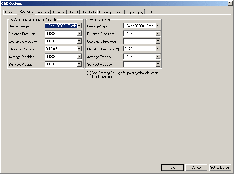
Rounding tab
Allows you to specify the rounding settings for various types of
numbers for the print file text and for the drawing text.
Note: All internal
calculations are performed with double precision accuracy. Only the
output is rounded.
When you select the Rounding tab , you will see the
following dialog:
The Rounding dialog has a
section for At Command Line and in
Print File rounding settings and a section for Text in Drawing rounding settings. Both
sections have similar settings but they apply to different
output. At Command Line and
in Print File rounding settings effect all output to the
command line and the print file. Text in Drawing rounding settings
effect numeric text placed in the drawing.
Angular precision can be specified to the nearest:
Angles in Degrees
or Angles in Grads
0.1 Second
0.000001 Grad
Second
0.00001 Grad
5 Seconds
0.0001 Grad
15 Seconds
0.001 Grad
30 Seconds
0.01 Grad
Minute
0.1 Grad
Distance precision can be specified to the nearest:
Foot (or Meter)
0 (no decimal places)
Tenth of Foot (or Meter)
0.1
Hundredth Foot (or Meter)
0.12
Thousandth Foot (or Meter)
0.123
Ten Thousandth Foot (or Meter)
0.1234
Hundred Thousandth Foot (or Meter)
0.12345
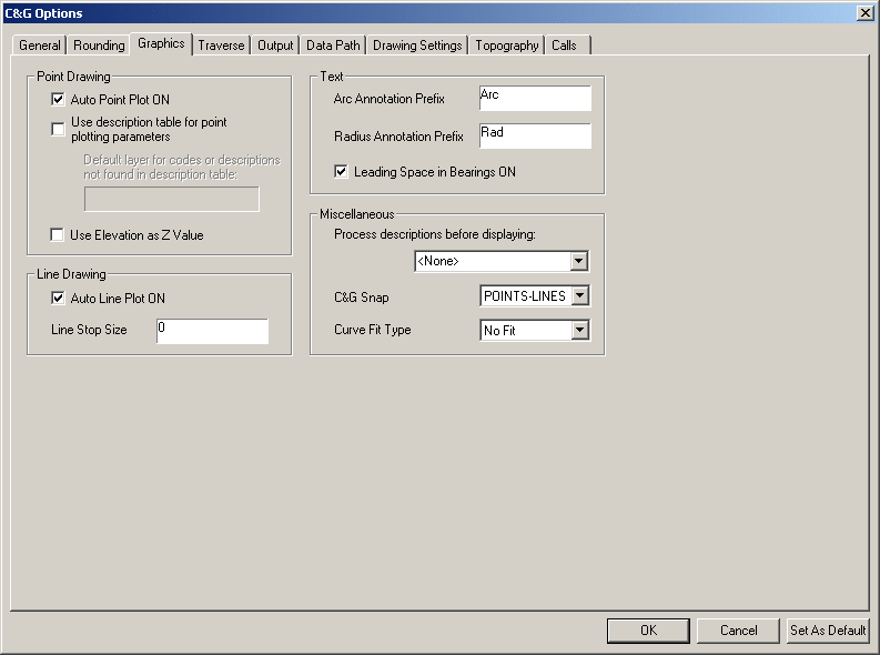
Graphics tab
The Graphics tab settings
apply only to CGSurvey features that draw points, lines, etc. to
the drawing. When you select the Graphics tab, the following dialog will
appear:
Point Drawing
section
Auto Point Plot ON if
the Auto Point Plot ON
checkbox is checked, points symbols will be drawn as they are
calculated and saved to the coordinate file by the various C&G
features.
Use Description table for point
plotting parameters When this checkbox is checked the
description(s) for a given point in the coordinate file will
be matched with the descriptions in the description table. If
a match is found then the description table information will be
used to set the layer, symbol type, symbol size, and label
positions of each point plotted. If no descriptions in the
description table match then the layer will be set to the layer
specified in the Default layer for
codes or descriptions not found in description table edit
box and the other settings specified in the Drawing Settings tab will be used (see
below).
If the Use Description table for
point plotting parameters checkbox is not checked, the
points, symbols and labels will be plotted on the Current Layer as
set in the CAD layer manager.
Default layer for codes or
descriptions not found in description table: When the
Use description table for point
plotting parameters checkbox is checked, any points plotted
that do not have a description or having a description that does
not match any of those in the description table, will be plotted on
the layer you have specified as the default layer in this edit
box.
Use Elevation as Z Value:
If this checkbox is checked, objects (lines/arcs/points) will be
placed in 3-D space with the point elevation serving as the
Z-value. C&G features, such as intersects and inverse, ignore
the Z-value of lines and arcs. If you inverse a 3-D line, the 2-D
distance between the points will be shown.
If the Use Elevation as Z
Value checkbox is not checked, all objects will be placed at
zero elevation.
Note: 3D lines can cause
problems in trimming or editing using CAD functions. 3D lines
do not intersect if their elevations are different. Thus two
lines may appear to intersect in plan view but do not actually
intersect in 3D space.
Line Drawing section
Auto Line Plot ON If the
Auto Line Plot ON checkbox is checked, those features that create
points that can be interpreted as a line will draw C&G
lines.
The following features can draw lines and curves as the points are
calculated:
Quick Traverse (not to side shots)
Curve Between Tangents and
Tangent Between Curves
Bearing and Hinge/Radial Area-Cut-Off
Roadways (Right of Way/Easements and Intersections/Cul-de-Sacs)
Middle Ordinate
Solution
Best Fit
Line Stop Size This allows
you to terminate C&G lines at the edge of the point symbols
plotted. If you are drawing lines and/or arcs with a C&G
feature that draws lines and you want the line to end before
crossing into the symbol, then set the Line Stop Size to the symbol size.
Note: If you set the line
stop to something other than 0.0, the line that is drawn is shorter
than the actual distance between the coordinate points. So if
you wish to check the true distance of that line, use the
Query command (on the Draw
menu) rather than the CAD LIST command.
Text section
Arc Annotation Prefix
This is used when annotating arcs when drawing calls. This should
be set to the desired prefix for arc length annotation.
Example:
“Arc =“ annotation prefix results in the annotation being
Arc = 256.32
“A =“ annotation prefix results in the annotation being
A = 256.32
Radius Annotation
Prefix
This is used when annotating arcs when drawing calls. Similar to
Arc Annotation Prefix, This
should be set to the desired prefix for radius annotation.
Leading Space in
Bearing
When the Leading Space in
Bearing checkbox is checked the bearing text has a space
between the N or S and the degrees text (eg, N 85º15’30"E).
When left unchecked there is not space (eg, N85º15’30"E).
Miscellaneous section
Process Descriptions before
Displaying:
This setting will allows you to specify how descriptions are
processed prior to being displayed. It allows the removal of
all underscores (_) and/or mapping codes. No change is made
to the data in the coordinate file.
C&G Snap can be set
to:
Off: No snap.
POINTS - Snap to C&G
point symbols and labels.
LINES - Snap to C&G
lines.
POINTS-LINES - Snap to
C&G points and lines.
All C&G functions will use this setting when you are picking
point symbols, point labels, lines, and arcs on the screen.
Curve Fit Type
When contouring, the contour lines that are created can
be smoothed using one of the following methods:
No Fit - Straight line
segments between the points.
Fit - Use the CAD program's
standard fit method. Contours may not pass through point
symbols having the same elevation as the contour.
C&G Spline - Use the
C&G Spline Fit algorithm. Contours are guaranteed to pass
through point symbols having the same elevation as the contour.
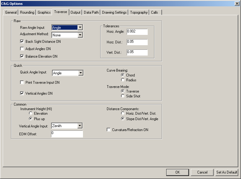
Traverse tab
These settings are specific to traverse raw data entry using the
CGEditor and the traverse reduction and quick traverse
features.
Raw section
Raw Angle Input
This allows you to specify how you want to specify angles when
inputting raw traverse data. The options are: Angle, Azimuth or Deflection Angle.
Adjustment Method
You have the following choices for
traverse adjustment:
None
Least Squares (NOT network
least squares - see SurvNET
for that)
Find Bad Angle
Compass
Transit
Crandall
Note: See the Reduce Traverse feature help section
for more details on these methods.
If the Backsight Distance
ON checkbox is checked and you entering raw traverse data,
you must specify the distance to the backsight at each instrument
point. These distances will then be used during the reduction
process.
If the Adjust Angles ON
checkbox is checked, angles will automatically be balanced prior to
traverse adjustment. Angular error will be spread equally
between all points. Closure information prior to and after
balancing will be displayed at the command line.
If the Balance Elevations
ON checkbox is checked, the elevations in a 3-D traverse
will automatically be balanced during traverse adjustment. The
elevations are adjusted proportional to the length of the traverse
legs.
Tolerances section
Horz. Angle.
When comparing multiple angles for
a given foresight point from a given instrument point and backsight
point, this value will be used as the maximum acceptable angular
error. If the difference between any two angles is greater than the
acceptable limit, the reduction process will pause and showing the
instrument point ID and angle measurements will be displayed at the
command line.
Horz. Dist.
When comparing multiple horizontal
distance components or measurements to a single foresight point,
this value will be used as the maximum acceptable distance
difference. If the difference between any two distances is greater
than this limit, the reduction process will pause and the
instrument point ID and the involved distances will be displayed at
the command line.
The horizontal distance tolerance is also used as the maximum
allowable difference between the two calculated curve radii at the
curve end points. If the difference between the distances from the
radius point to the PC point and the radius point to the PT point
is greater than this value, the calculations will be terminated
with an appropriate error message.
Note: for curves, if this
value is set unreasonably low, many curves will produce this error
message. If you change the setting to a larger, more
reasonable value, the curve can be recalculated and generated
without error.
Vert. Dist.
This value is the maximum
acceptable elevation difference. It is used when comparing
multiple vertical distance components/measurements to a given
foresight point from a given instrument point. If the difference
between the distances is greater than this limit, the reduction
process will pause, showing you the instrument point ID and the
involved distances. This only applies to the reduction of a 3-D
traverse.
Quick section
Quick Angle Input
This specifies the default angle input mode for the Quick Traverse
Feature. This can be changed when using the Quick Traverse feature.
The angle input modes are:
Angle
Deflection Angle
Azimuth
Bearing
If the Print Traverse Input
ON checkbox is checked, all raw input data will be displayed
along with the traverse output. If this checkbox is not
checked, only the traverse output will be printed.
If the Vertical Angles ON
checkbox is checked you will be asked to enter vertical
angles with the traverse distances. This can be changed when
using the Quick Traverse
feature.
Curve Bearing
This defines how non-tangent curve bearings will be input and can
be set to either Chord or
Radius depending on how you
wish to define the orientation of non-tangent curves.
When set to Chord and you
are traversing around a non-tangent curve, you must enter the
bearing or angle from the PC to the PT.
When set to Radius and you are traversing around a non-tangent
curve, you must enter the bearing or angle from the PC to the
radius point.
Curve Tables and printed calculations will reflect this
setting.
Traverse Mode
Sets the default traverse mode for the Quick Traverse feature.
It can be set to Traverse
or Side Shot mode .
Traverse mode: as a
point is created the new point is occupied and backsight the
previously occupied point.
Side Shot mode: as a point
is created the currently occupied point and backsight will be
held.
Common section
Instrument Height (HI)
The value entered for the HI can be either the actual instrument
Elevation or the distance
from the ground to the instrument (Plus up). In the latter case the
elevation of the point the instrument is over is read from the
coordinate file and the instrument height is added to it to
determine the instrument elevation.
Vertical Angle Input - can
be set to one of the following, depending on the type of instrument
used:
Zenith: Zero angle up
Nadir: Zero angle down
Transit: Zero angle level
Note: If set to Transit, vertical can
either be full circle (0 to 360 degrees; 0 to 400 grads) or
positive angle up and negative angle down.
EDM Offset
Depending on where your EDM is mounted, enter the vertical
difference between the center of the scope of the instrument and
the center of the beam of the EDM (+ if EDM is above; - if EDM is
below). Do not use an EDM Offset for scope mounted EDM’s. This
offset should only be applied to yoke or azimuth base mounted
EDM’s.
Note: Use of the EDM offset allows you
to turn your vertical angles directly to the target. A correction
will be applied to all distances and elevations computed from field
entries in the Traverse and Quick Traverse routines. Most total
stations today have the EDM coincident with the center line of
instrument scope. In this case the EDM Offset should be set to
zero.
Note: When an offset is
entered, it is used on all distances in the traverse. If some
distances are chained, the correction will also be applied. These
shots should be reduced separately with no EDM Offset.
Distance Components - This
option can be set to allow either Slope Distance/Vertical Angle or
Horizontal Distance/Vertical
Distance data entry.
If the Curvature and Refraction
ON check box is checked, the horizontal and vertical
components of all slope distances are corrected for curvature and
refraction. If your EDM does not already make this correction, it
is recommended that this correction be used when carrying
elevations using vertical angles and distances.
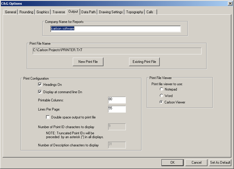
Output tab
This tab allows you to specify the name and format of the print
file and how it is viewed.
Print File Name section
The final results of calculations and other actions performed
during C&G command execution will always be printed to this
ASCII text file. New information is always appended to this file
and never overwritten. The default file name is PRINTER.TXT. It is
recommended that you use a name that corresponds with the project
you are working on. This way you will have a record of all
calculations throughout the project. Use the New Print File button to specify a new
print file to create. Use the Existing Print File button to specify
an existing file.
Print File Viewer section
You can choose to use Microsoft Notepad or Wordpad when viewing or
printing the print file. If you want the viewer to always
come up full screen, check the Force print file viewer to use full
screen checkbox.
Point Configuration section
If the Headings On checkbox
is checked, a heading is printed to the command line and/or the
print file any time multi-line output is generated by a C&G
feature. The heading information contains date, time, feature
name, coordinate file name and input and output scale
factors. The header is repeated when the number of lines
output by a function exceed the value set for Lines Per Page.
If the Display On checkbox
is checked, the output from CGSurvey features is printed at the
command line. Regardless of this setting, output is always sent to
the print file.
Printable Columns
Use the edit box to specify the maximum number of characters per
line to be written to the print file. This allows you to fit
the text to the printed page given the font and paper your
uses. The acceptable values are 80 through 255.
Lines Per Page
This allows you to set the number of lines that will be placed on a
page. If headings are on, a header will be printed to the
print file and the command line each time this number of lines is
exceeded.
Data Path tab
On this tab you can specify the path to your data files. The
data path is the default directory for file dialogs used in various
C&G commands that open or save files.
You can type the path in the Data
Path edit box or you can use the Browse... button to use a file dialog
to specify the data path.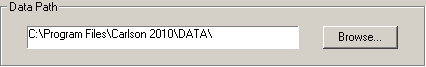
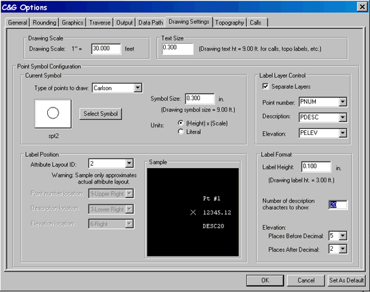
Drawing Settings
tab
On this tab you can specify drawing scale, text size, point symbol
type and its format, and point symbol layers.
Drawing Scale section
This sets the horizontal scale. For example, if units are set to
feet and you want a horizontal scale of 1" = 20' then type 20 in
the Horizontal (ft/in) edit box. For metric units, if you
want a scale of 1m = 500m then enter 500 in the Horizontal (m/m)
edit box
Text Size section
Allows you to set the text size for any text drawn using a CGSurvey
feature. The text size is the size of the text as measured on
the plotted or printed page. It must be specified in inches
if using feet or centimeters if using meters.
Point Symbol Configuration section
Current Symbol section
This section allows you to control the symbol, its size and how it
is scaled (called units here).
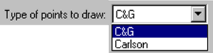
Type of Point to be Drawn:
There are two point symbol libraries to select symbols from, the
C&G and the Carlson symbol libraries.
Using symbols from either the C&G or Carlson symbol library
both allow you to use all of the associated C&G features for
plotting, sorting, line stops, attribute information, selection,
etc. If you choose to use Carlson symbols the Label Position
section of the dialog changes somewhat. This will be
discussed later in this section.
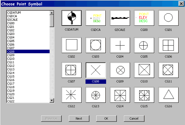
Select Symbol button
Choosing Select Symbol
button will bring up the Choose
Point Symbol dialog:
Use this dialog to choose the active point symbol. You do this by
highlighting the symbol name in the list on the left or by clicking
the symbol image on the right. Symbols CG00 and CGDCA are
compatible with LDT/LDD points. The CGDCA symbol is the correct
size for a true LDT/LDD point, and should be used if you are also
using LDT/LDD.
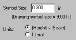
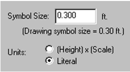
Symbol Size and Units
There are two options available for specifying symbol size:
(Height) X (Scale) and
Literal
If Units are set to
(Height)x(Scale), then the
symbol size entered here is specified as plotted page units (inches or
centimeters - depending on whether feet or meters are being
used). In this case, regardless of scale, the symbol will
always be the same size when plotted. In example above, the
symbol is set to .300”. At 30 scale the symbol height will be
9 feet in the drawing itself, at 40 scale it would be 12
feet. Thus, in either case, its plotted size will be 0.3
inches.
If Units are set to
Literal then the symbol
will be drawn in the
drawing at the size specified. This setting is often
used for inserts such as title blocks, north arrows, company logos,
standard notes, etc.
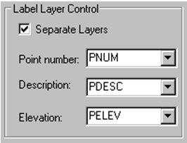
Label Layer Control section
If you check the Separate Layers check box, you can assign each
point label to a specific layer. This allows you to see only the
labels you want by turning different layers on or off. If this
checkbox is not checked, all the point labels will be drawn on the
current layer.
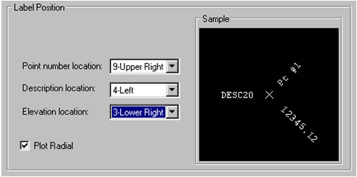
Label Position section
C&G Labels:
If the label location is set to 0
<Off> that label will not be displayed when a point is
plotted. Only the elevation is allowed to be at the
Center position. If
you select Center for the elevation label, the whole number portion
of the elevation will be on the left side of the insertion point of
the symbol and the decimal portion on the right side (example: the
elevation 987.23 will be drawn as 987+23, where the plus sign
represents the symbol).
If Plot Radial is checked,
the point labels will be plotted radially from the symbol’s center.
If not selected, point labels will be plotted horizontally.
Label Position for Carlson Symbols
In the Point Symbol
Configuration section of the dialog you have the option to
plot C&G symbols or Carlson symbols. When the Carlson
symbols are used, the Label
Position portion of the dialog box changes to display the
Carlson method for defining label positions (see below).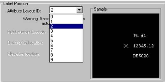 These "label positions" are actually pre-defined blocks with a
predefined location and orientation for the attributes (or
labels). There are ten blocks available. The available
blocks are identified by the numbers 0 through 9.
These "label positions" are actually pre-defined blocks with a
predefined location and orientation for the attributes (or
labels). There are ten blocks available. The available
blocks are identified by the numbers 0 through 9.
Note: when Carlson point
symbols are used, the Sample drawing is only approximate - the
actual layout will look slightly different when drawn.
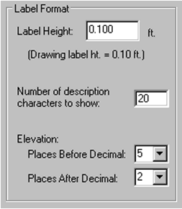
Label Format section
Label Height: this is
the text size in inches/centimeters when Units are set to (Height) x (Scale) or feet/meters when
Units are Literal. The Label Height is used for all three
labels: point number, point description, and point elevation.
Number of description characters
to show: Depending on the type of coordinate file being
used, here may be as many as 255 characters in the description
field. This option allows you to truncate the description at
a given number of characters.
Elevation: This sets
how many characters are displayed before and after the decimal
point. On a flat piece of property 2 placed before the
decimal may be enough information. On a steep mountain site 3
or 4 decimal places may be needed.
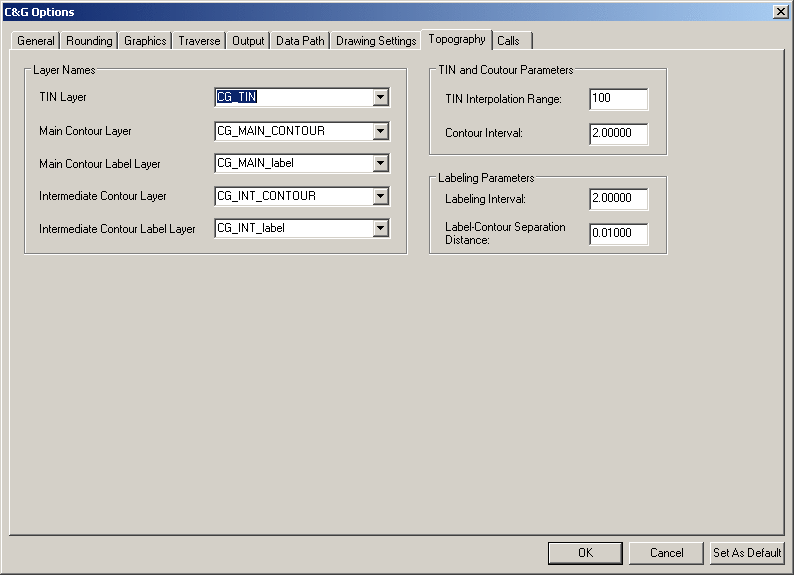
Topography tab
NOTE: The information
on this tab is used for items on the CGTopo menu which has limited
functionality and does not allow you to create a TIN. You must use
the Carlson features to make, use and manipulate TINs (see Surface
menu). These settings may be used when opening a CG-SURVEY
for DOS drawing (*.PL1) when it has topo data in it.
The items on this tab allow you to specify contouring parameters
and Tin, contour and other topographic entity layer
specifications.
This dialog allows you to specify the drawing layers for the
various topographic entities, as well as set various parameters for
the creation of a new surface and placement of contour elevation
labels.
Layer Names section
In this part of the dialog you can specify the layers for the
various previously existing topographic entities found in the
drawing. These allow you to label contours and, if necessary,
remove contours and/or labels from the drawing.
TIN Layer: Specifies the layer on which triangulation
network lines or TIN are found.
Main Contour Layer: Layer
on which main contours are found.
Intermediate Contour Layer:
Layer on which intermediate contours are found.
Main Contour Label Layer -
Elevation labels for the main or index contour lines will be drawn
on this layer.
Intermediate Contour Label
Layer - Elevation labels for the intermediate contour lines
will be drawn on this layer.
Note: The last two Contour
Label Layer names will be used when labeling contours.
TIN and Contour Parameters section
TIN Interpolation
Range: The interpolation range determines which points
will be joined to form the triangles in the TIN. (MAY be used
converting a CG-SURVEY for DOS PL1.)
Contour Interval: (MAY be
used converting a CG-SURVEY for DOS PL1.).
Labeling Parameters section
Label Interval: When
labeling contours, only the contours falling on this interval will
be labeled. For example, if you enter a 10' interval, only the
contours at 900, 910, 920, etc will be labeled.
Label-Contour Separation
Distance: This is the space between each end of the
elevation label text and the contour line being labeled. A
separation distance that is too small can make the elevation label
hard to read, while a separation distance that is too large may not
be visually pleasing.
Calls tab
This tab gives you several options for specifying the call or
annotation format
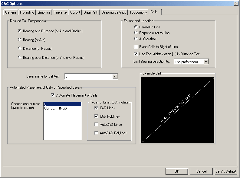
Desired Components
section
The of the dialog allows you
to specify what you want displayed for a given call and whether the
call text is stacked. The text in parentheses indicate the
call items for a curve.
Format and Location
section
The allows you to specify whether the call is placed
Parallel to Line,
Perpendicular to Line or
requires the user to pick the location for horizontal call text
(
At Crosshair). If
the
Place Calls to Right of
Line checkbox is checked the calls will be placed on the
right side as determined by standing at the first point picked or
the first point in a C&G line and looking toward the second
point. You may also specify whether to use the foot symbol
when units are feet. If bearings are being used, you may
specify whether to limit bearing text to
NW,NE only or
SW, SE only or
<no preference>.
Layer name for call
text:
Specify the layer the call text is to be drawn on.
Automated Placement of Calls
on Specified Layers section
This section of the dialog sets the parameters for a feature that
allows you to place calls on C&G and/or CAD lines and/or
polylines found on specified layers. To use this option,
check the
Automate Placement of
Calls checkbox. Choose one or more layer names from
the list of layer names. You can specify multiple layers by
holding the Ctrl key down while picking the layers to
search.
In the
Types of Lines to
Annotate section, check the types of entities you wish to
annotate.
Example Call
section
The of the tab allows you to see a good approximation of how
the call will look when drawn.
C&G Options dialog buttons
OK - click the
OK button to save all the settings and
close the dialog.
Cancel - click the
Cancel button to close the
dialog and discard any changes.
Set As Default
Click this button to save the
settings to the CGSURVEY.OPT file. These settings will then
be used whenever a new CGSurvey drawing is created.
Note: You can set the
default settings and not affect any of the settings for the current
drawing by clicking the Cancel button after clicking the
Set As Default button.
Pulldown Menu Location:
CG-Survey > Tools
Keyboard Command:
cg_options
Prerequiste: None