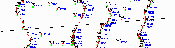
This command creates a cross section of a solid. The cross
section is either drawn as a 3D polyline or stored to a SCT file
and assigned to a station. Use commands like Draw Section File to
view the cross section SCT file.
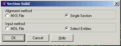
The section alignment can be defined by MXS File for
creating sections for multiple stations. Use the Pick Points
method for a single section. With this single section, the program
prompts for two points to define the alignment for the cross
section. The Elevation Values and Elevation Interval
methods create horizontal sections of the solid which is like
contouring the solid.
The solid model can be defined by a Carlson 3D Model file (MDL)
or by 3D Solid entities in the drawing.
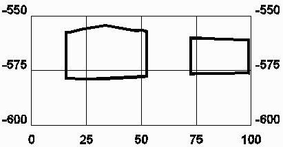 Cross section of solid model
Pulldown Menu Location: Solid in Underground Mining and
Section in Civil
Keyboard Command: section_solid
Prerequisite: solid model file or 3D Solid entities