SurvNet works equally well for both Carlson users and C&G users. The primary difference between the two users is that a Carlson user will typically be using an .RW5 file for his raw data and a C&G user will typically be using a .CGR file.
SurvNet is capable of
processing either C&G (.CGR) raw data files, Carlson (.RW5) raw
data files or SDMS (.PRJ) raw data files. If the raw data is in
another format, you can use our conversion tools to create one of
the supported formats.
Measurement, coordinate, elevation and direction (Brg/Az) records are all recognized. Scale factor records in the .CGR file are not processed since SurvNet calculates the state plane scale factors automatically.
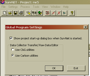
The menu option "Settings->Global Settings" displays the following dialog box. If the 'Use Carlson Utilities' is chosen then the .RW5 editor will be the default raw editor and Carlson SurvCom will be the default data collection transfer program. If the 'Use C&G Utilities' is chosen then the C&G .CGR editor will be the default raw editor and C&G's data collection transfer program will be the default data collection transfer program.
Standard errors are estimated errors that are assigned to measurements or coordinates. A standard error is an estimate of the standard deviation of a sample. A higher standard error indicates a less accurate measurement. The higher the standard error of a measurement, the less weight it will have in the adjustment process.
Although you can set default standard errors for the various types of measurements in the project settings of SurvNet, standard errors can also be placed directly into the raw data file. A standard error record inserted into a raw data file applies to all the measurements following the SE record. The standard error does not change until another SE record is inserted that either changes the specific standard error, or sets the standard errors back to the project defaults. The advantage of entering standard errors into the raw file is that you can have different standard errors for the same type measurement in the same job. For example, if you used a one second total station with fixed backsights and foresights for a portion of a traverse and a 10 second total station with backsights and foresights to hand held prisms on the other portion of the traverse, you would want to assign different standard errors to reflect the different methods used to collect the data.
Make sure the SE record is placed before the measurements for which it applies.
If you do not have standard errors defined in the raw data file,
the default standard errors in the project settings will be applied
to the entire file.
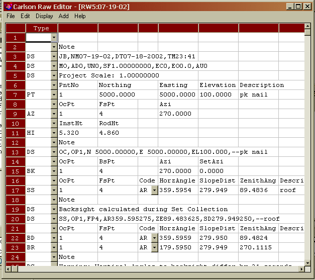
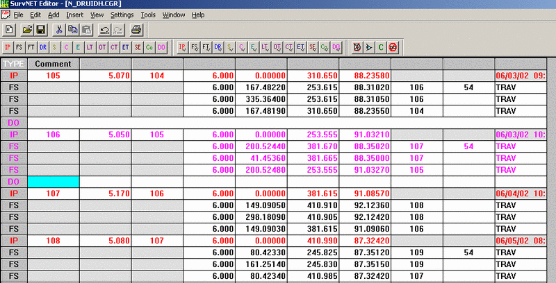
The raw data editor can be accessed from the tool bar icon. Following is an image of the .RW5 editor. Refer to the Carlson raw editor documentation for guidance in the basic operation of the editor. The following documentation only deals with topics that are specific to the .RW5 editor and SurvNet.
You can insert or add Standard Error records into the raw data
file. Use the 'Add' menu option to insert standard error records
into the raw files.
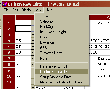
You can set standard errors for Northing, Easting, Elevation, and Azimuth using the 'Control Standard Error' menu option. Azimuth standard errors are entered in seconds. The North, East and Elevation standard errors affect the PT (coordinate) and EL (elevation) records.
You can hold the North, East and Elevation fixed by entering a "!" symbol. You can allow the North, East and Elevation to FLOAT by entering a "#" symbol. You can also assign the North, East and Elevation actual values. If you use an "*" symbol, the current standard error value will return to the project default values.
North East
Elevation
Azim
!
!
!
(Fix all values)
#
#
#
30.0 (Allow the N.,
E. & Elevation to Float)
0.01
0.01
0.03
5.0 (assign
values)
*
*
*
* (return the
control standard errors back to project defaults)
When you fix a coordinate point, the original value does not change during the adjustment and all measurements will be adjusted to fit the fixed point. If you allow a value to float, it will not be used in the actual adjustment, it will just be used to help calculate the initial coordinate values required for the adjustment process. Placing a very high or low standard error on a coordinate point accomplishes almost the same thing as setting the standard error as float or fixed. The primary purpose of using a float point is if SurvNet cannot compute preliminary values, a preliminary float value can be computed and entered for the point.
Direction records cannot be FIXED or FLOAT. You can assign a low
standard error (or zero to fix) if you want to weight it heavily,
or a high standard error to allow it to float.
In the example below, the first SEc record containing the '!'
character and sets points 103, 204, and 306 to be fixed. The last
SEc record contains the '*' character. It sets the standard errors
for point 478 and any other points that follow to the project
settings. The Azimuth standard error was left blank.
Example:
North East Elev Azim
CSE
!
!
!
PT 103 1123233.23491
238477.28654 923.456
PT 204 1124789.84638
239234.56946 859.275
PT 306 1122934.25974
237258.65248 904.957
North
East
Elev Azim
CSE
*
*
*
PT 478 1122784.26874
237300.75248 945.840
You can set the standard errors for distances, horizontal angle pointing, horizontal angle reading, vertical angle pointing, vertical angle reading, and distance constant and PPM.
"Distance" - distance constant and measurement error, can be obtained from EDM specs, or from performing an EDM calibration on an EDM baseline, or from other testing done by the user.
"PPM" - Parts per Million, obtain from EDM specs, or from performing an EDM calibration on an EDM baseline, or from other testing done by the user.
"Pointing" - total station horizontal angular pointing error in seconds. This value is an indication of how accurately the instrument man can point to the target. For example, you may set it higher in the summer because of the heat waves. Or you may set it higher for total stations running in Robotic Mode because they cannot point as well as a manual sighted total station.
"Reading" - total station horizontal angular reading error in seconds. If you have a 10 second theodolite, enter a reading error of 10 seconds.
"V.Pointing" - total station vertical angular pointing error in seconds. This value is an indication of how accurately the instrument man can point to the target. For example, you may set it higher in the summer because of the heat waves.
"V.Reading" - total station vertical angular reading error in seconds. If you have a 10 second theodolite, enter a reading error of 10 seconds.
Example:
Distance Point Read V.Point V.Read PPM
MSE 0.01 3 3 3 3 5
You can enter any combination of the above values. If you do not want to change the standard error for a particular measurement type, leave it blank.
If you use an "*" symbol, the standard error for that measurement type will return to the project default values.
These standard errors are a measure of how accurately the instrument and target can be setup over the points.
"Rod Ctr" is the Target Centering error. This value reflects how accurately the target prism can be set up over the point.
"Inst Ctr" is the Instrument Centering error. This value reflects how accurately the instrument can be set up over the point.
"Ints Hgt" is the Instrument Height error. This value reflects how accurately the height of the instrument above the mark can be measured.
"Rod Hgt" is the Target Height error. This value reflects how accurately the height of the prism above the mark can be measured.
Example:
Rod Ctr Inst Ctr Inst Ht Rod Hgt
SSE
0.005
0.005
0.01
0.01
You can enter any combination of the above values. If you do not want to change the standard error for a particular measurement type, leave it blank.
If you use an "*" symbol, it will
return the standard error to the project default values.
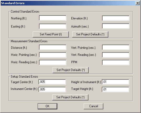
You can set standard errors for control, measurements and instrument setup using the Insert->Standard Error menu option:
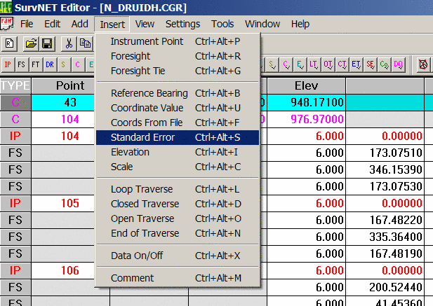
This will open a Standard Error dialog box:
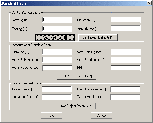
This dialog allows you to create three types of
standard error records: Control, Measurement, and Setup. You need
only enter the values for the standard errors you wish to set. If a
field is left blank no standard error for that value will be
inserted into the raw data file.
You can hold the North, East and Elevation fixed by entering a "!" symbol (as shown above). You can allow the North, East and Elevation to FLOAT by entering a "#" symbol. You can also assign the North, East and Elevation actual values. If you use an "*" symbol (or press the "Set Project Defaults" button), the current standard error value will return to the project default values.
In the above example, a Control Standard Error record (SEc) will be created:
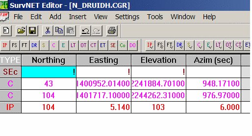
Below are some sample values for control standard errors:
North East
Elevation
Azim
!
!
!
(Fix all values)
#
#
#
30.0 (Allow the N.,
E. & Elevation to Float)
0.01
0.01
0.03
5.0 (assign
values)
*
*
*
* (return the
standard errors back to project defaults)
When you fix a coordinate point, the original value does not change during the adjustment and all other measurements will be adjusted to fit the fixed point. If you allow a value to float, it will not be used in the actual adjustment, it will just be used to help calculate the initial coordinate values required for the adjustment process. Placing a very high or low standard error on a measurement accomplishes almost the same thing as setting a standard error as float or fixed. The primary purpose of using a float point is if SurvNet cannot compute preliminary values, a preliminary float value can be computed and entered for the point.
Direction records cannot be FIXED or FLOAT. You can assign a low
standard error (or zero to fix) if you want to weight it heavily,
or a high standard error to allow it to float.
You can set the standard errors for distances, horizontal angle pointing, horizontal angle reading, vertical angle pointing, vertical angle reading, and distance constant and PPM.
"Distance" - distance constant and measurement error, can be obtained from EDM specs, or from performing an EDM calibration on an EDM baseline, or from other testing done by the user.
"PPM" - Parts per Million, obtain from EDM specs, or from performing an EDM calibration on an EDM baseline, or from other testing done by the user.
"Pointing" - total station horizontal angular pointing error in seconds. This value is an indication of how accurately the instrument man can point to the target. For example, you may set it higher in the summer because of the heat waves. Or you may set it higher for total stations running in Robotic Mode because they cannot point as well as a manual sighted total station.
"Reading" - total station horizontal angular reading error in seconds. If you have a 10 second theodolite, enter a reading error of 10 seconds.
"V.Pointing" - total station vertical angular pointing error in seconds. This value is an indication of how accurately the instrument man can point to the target. For example, you may set it higher in the summer because of the heat waves.
"V.Reading" - total station vertical angular reading error in seconds. If you have a 10 second theodolite, enter a reading error of 10 seconds.
Example:
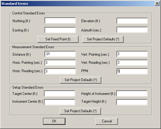
You can enter any combination of the above values. If you do not want to change the standard error for a particular measurement type, leave it blank. If you use an "*" symbol, the standard error for that measurement type will return to the project default values.
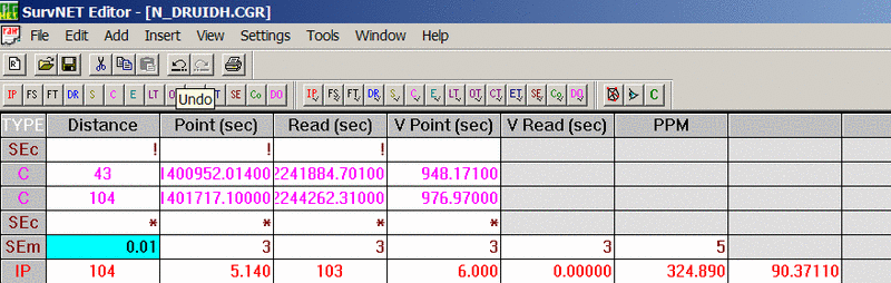
The following SEm
record will be created:
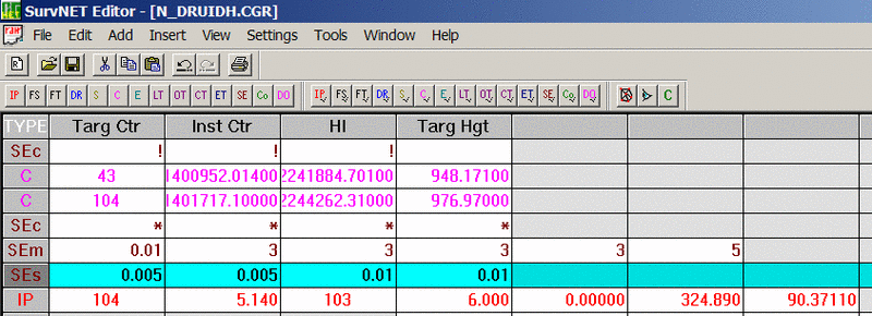
These standard errors are a measure of how accurately the instrument and target can be setup over the points.
"Target Center" is the Target Centering error. This value reflects how accurately the target prism can be set up over the point.
"Instrument Center" is the Instrument Centering error. This value reflects how accurately the instrument can be set up over the point.
"Height of Instrument" is the Instrument Height error. This value reflects how accurately the height of the instrument above the mark can be measured.
"Target Height" is the Target Height error. This value reflects how accurately the height of the prism above the mark can be measured.
Example:
You can enter any combination of the
above values. If you do not want to change the standard error for a
particular measurement type, leave it blank.
If you use an "*" symbol, it will return the standard error to the
project default values.
The following SEs record will be
created:
There are several other features
available in both the Carlson and C&G editors that are useful
to SurvNet.
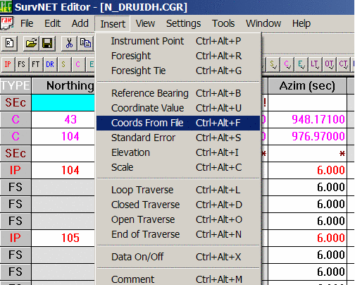
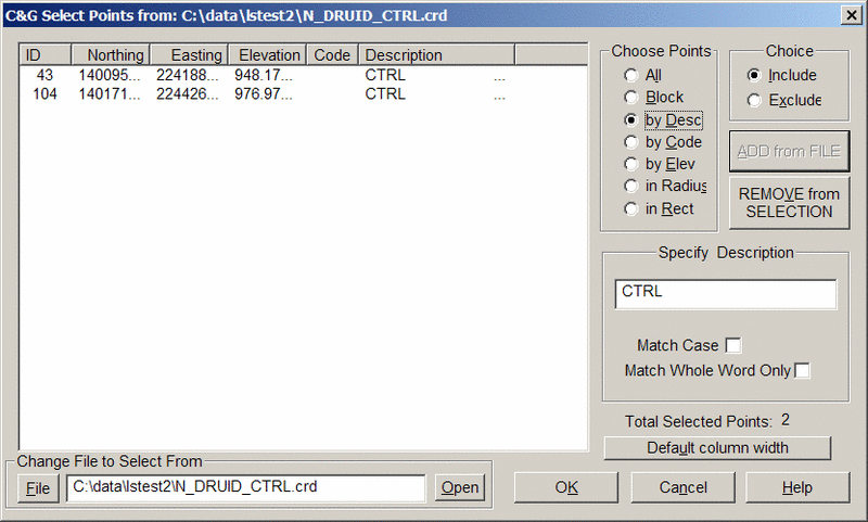
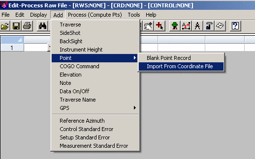
Insert Coordinate records from file - when inputting control into a raw data file, it is more convenient to read the control point directly from a coordinate file than it is to manually key them in. The "Insert Coordinates" function allows you to select points in a variety of manner making it easy to select just control points. For example, you can select points by description, code, point blocks, point number, etc.
Data ON/OFF records - when trying track down problems, sometimes it is convenient to remove certain sections of raw data prior to processing. Both the Carlson and C&G raw data editors have a special record (DO record) that will turn OFF or ON certain areas of data. For example, when you insert a DO record all data following that record will be turned OFF (it will be shown in a different color). When you insert another DO record further down, the data following it will be turn back ON. It is simply a toggle.
One of the benefits of SurvNet is the ability to process redundant measurements. In terms of total station data redundant measurement is defined as measuring angles and/or distances to the same point from two or more different setups.
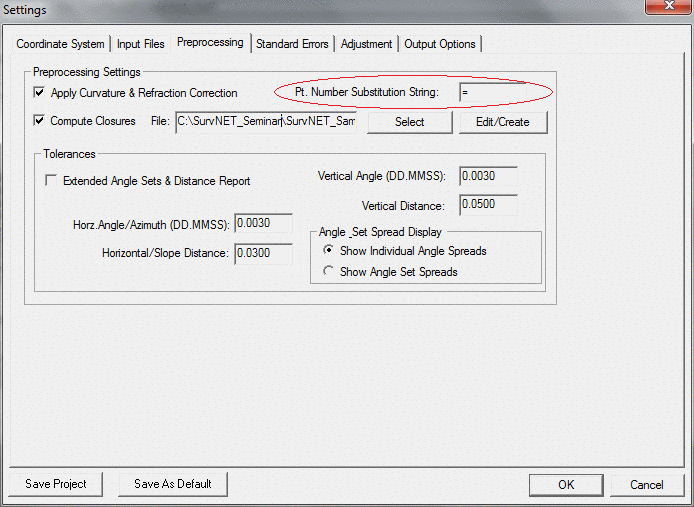
It is required that the same point number be used when locating a point that was previously recorded. However, since some data collectors will not allow you to use the same point number if the point already exists, we use the following convention for collecting redundant points while collecting the data in the field. If the point description contains a user defined string, for example a "=" (equal sign) followed by the original point number, we will treat that measurement as a redundant measurement to the point defined in the description field. The user defined character or string is set in the project settings dialog. For example, if point number 56 has the description "=12", we will treat it as a measurement to point 12 and point 56 will not exist. Make sure the Preprocessing Settings dialog box has the Pt. Number Substitution String set to the appropriate value.
Alternately, the point numbers can be edited after the raw data has been downloaded from the data collector.
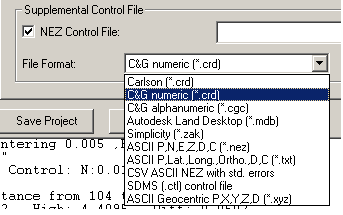
In order to process a raw data file, you must have as a minimum a control point and a control azimuth, or two control points. Control points can be inserted into the raw data file or alternately control points can be read from coordinate files. Control points can be read from a variety of coordinate file types:
C&G or Carlson numeric (.CRD)
files
C&G Alphanumeric coordinate files (*.cgc)
Carlson Alphanumeric coordinate files (*.crd)
Carlson SQLITE (*.crdb)
Autodesk Land Desktop (*.mdb)
Simplicity coordinate files (*.zak)
ASCII (.NEZ) file
ASCII latitude and longitude (3D model only)
CSV ASCII NEZ with std. errors (only external control file that
allows you to assign standard errors to specific points).
SDMS (.ctl) control file
ASCII Geocentric Coordinates (.xyz) (Earth Centered Earth Fixed XYZ
coordinate values)
The standard errors for the control points from a supplemental control file will be assigned the NORTH and EAST standard errors from the project settings dialog box.
In the ASCII .NEZ file, the coordinate records need to be in the following format:
Pt. No.,
Northing,
Easting,
Elevation, Description<cr><lf>
103, 123233.23491, 238477.28654,
923.456, Mon 56-7B<CR><LF>
Each line is terminated with carriage-return <CR> and line-feed <LF> characters.
In the ASCII latitude and longitude file, the records need to be in the following format:
Pt. No.,
Latitude (NDDD.mmssssss), Longitude (WDDD.mmssssss), Elevation
(Orthometric), Description<cr><lf>
FRKN,N35.113068642,W083.234174724,649.27<CR><LF>
Each line is terminated with carriage-retu rn <CR> and line-feed <LF> characters.
In the ASCII XYZ Geocentric file, the records need to be in the following format:
Pt. No.
X Y Z Descriptions<cr><lf>
105 1413426.6020 -4537671.2000
4239299.9360 MON
Each line is terminated with carriage-return <CR> and line-feed <LF> characters
The major advantage
of putting coordinate control points in the actual raw data file is
that specific standard errors can be assigned to each control point
(as described in the RAW DATA section above). If you do not include
an SE record the standard error will be assigned from the NORTH,
EAST, and ELEVATION standard errors from the project settings
dialog box.
It is not allowed for the supplemental control file and the final
output file to be the same file. Since least squares considers all
points to be control points only control points should be in a
supplemental control file.