This command contains COGO routines for Inverse,
Occupy Point, Traverse, Side Shots, Bearing-Bearing Intersect,
Bearing-Distance Intersect, Distance-Distance Intersect and
Enter-Assign Point. Choosing Visual COGO from the COGO pull-down
menu provides you with quick access to any of the Visual COGO
routines.
A dialog for command input docks on the side of the
graphic window when any of the five options from the pulldown menu
are selected. Points are drawn to the screen as they are created.
Linework can also be drawn. CAD and Carlson commands can be
activated with the Visual COGO dialog active. This allows for quick
switching between Visual COGO commands and any other command. You
can also switch between Visual COGO commands within the dialog by
entering the 2 character function name in any edit box. For
example, from Visual COGO Inverse, you can enter SS in the point
number field to switch to Side Shots.
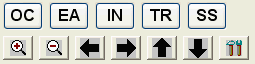
The function names OC, EA, IN, BB, BD, DD, TR and
SS are also available as function buttons across the top of the
dialog. The second row of buttons are functions for zooming in/out
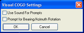
and panning. The final button brings up Visual Cogo options. The
Use Sound option is for
whether to have sounds cues. The Prompt for Bearing/Azimuth Rotation adds an
additional angle input in the Sideshot and Traverse functions. This
angle is added to the bearing or azimuth angle input and is a way
to handle North rotation where the orientation of the angles that
your entering is different than the target coordinate
system.
When in Visual COGO, you will have a very different user
interface from other areas of Carlson. This user-friendly screen
will guide you through various COGO data entry procedures such as
Inverse, Occupy Point, Traverse, Side Shots and Enter-Assign Point.
You will still be able to follow the command on the command line at
the bottom of your Carlson screen. Using Visual COGO is an
alternative and easy method to entering in such information. The
top half of the COGO pulldown menu offers you the more traditional
Carlson data entry method. Your results will be the same.
IN (Inverse): This command reports the bearing/azimuth and horizontal distance between two points. The points can be entered manually or by picking from a point list by picking on the list button. The resulting report of bearing/azimuth is dependent upon the Angle Mode setting in the drawing setup options.
OC (Occupy Point): Used to specify the point number of the instrument setup point. The point can be specified by manually entering in the point number in the Occupied Point data field, or by selecting the List button and choosing from the list of points contained in the coordinate file.
Backsight Method can be either by Point Number or by Azimuth. If angle right/left or deflection right/left is being used for traverse or sideshot entry, a backsight method must be specified. If using Bearing or Azimuth entry, no backsight method is required. The Backsight Point can be specified by manually entering in the point number in the Backsight Point data field, or by selecting the List button and choosing from the list of points contained in the coordinate file.
Instrument Height: Use this field to set the height of the instrument.
Accept (F2): Selecting this button or pressing the F2 function key accepts the data entered in the fields above. After accepting the data, until changed, the points specified will remain the occupied and backsight points. If the dialog is exited without Accepting the settings the Occupied and Backsight points will have to be specified when the OC dialog is revisited.
Exit: Cancels the command
TR (Traverse): This command allows data entry using any combination of turned angles, deflections, azimuths or bearings to define a traverse or figure. This command always occupies, moves up to, the last point it calculated and backsights the point before, or the previous occupied point.
Point Number: This is the number of the point to be created.
Rod Height: Height of target to be located.
The horizontal angle component can be input in various formats. The format label will change with the option chosen. Choose the format by selecting the down arrow and picking from the list.
The vertical angle component can be input in various ways (the
format label will change with the option chosen). Choose the format
by selecting the down arrow and picking from the list.
VA=Vertical Angle. Zero
(0) degrees is level.
ZE=Zenith Angle. Ninety (90) degrees is level.
DZ=Elevation Difference. The difference in elevation either plus or
minus from the instrument setup to the target.
The distance component can be entered as either
Slope or Horizontal Distance. Choose the format by selecting the
down arrow and picking from the list.
SD=Slope Distance
HD=Horizontal Distance
Distance can be defined by Point Numbers by selecting the calculator button to the far right of Angle Right and Slope Distance.
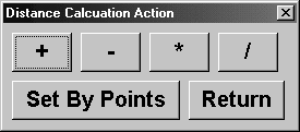
Additional mathematical calculations of addition, subtraction, multiplication and division can be performed on the input distance by selecting the appropriate button and filling out the function dialog.
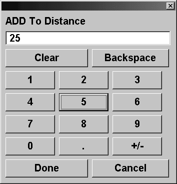
For example to add 25 to the Slope distance value on the traverse dialog, select the + button, enter 25 and then select Done. The same steps apply to any of the other mathematical functions.
Side Shots: This command works in the same way as the traverse command. All the available options contained in the traverse command are available in this command. The only difference in the commands is that the side shot command does not move the setup point to last shot input. Refer to the traverse command for further details.
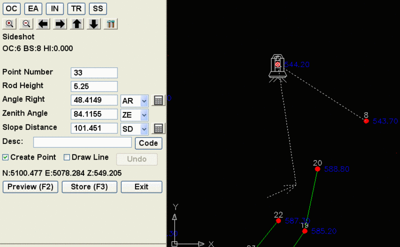
Desc: Defines the description for the point
to be created.
Create Point: Option whether to store the point to the CRD
file and draw a point.
Draw Line: Option to draw line to the traverse point.
Preview (F2): Previews the traverse point location, without
storing the point to the coordinate file.
Store (F3): Stores the traverse point based upon the entered
data to the coordinate file.
Undo: After storing the point, the point can be deleted from
the screen and coordinate file by selecting the undo button.
Exit: Exits the Visual COGO command and closes the dialog
box.
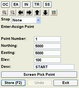
EA (Enter
Assign): Use this function
to enter and assign coordinate values for new and existing
points.
 BB
(Bearing-Bearing Intersect): Enter two base points along with the
angles from each and the routine calculates the bearing-bearing
intersection point. The dialog has fields for the output point
number and description.
BB
(Bearing-Bearing Intersect): Enter two base points along with the
angles from each and the routine calculates the bearing-bearing
intersection point. The dialog has fields for the output point
number and description.
BD (Bearing-Distance
Intersect): Enter two base points along with the angle from the
first and distance from the second and the routine calculates the
bearing-distance intersection point. The dialog has fields for the
output point number and description.
DD (Distance-Distance
Intersect): Enter two base points along with the distances from
each and the routine calculates the distance-distance intersection
point. For the two possible solutions of the intersecting circles,
the intersection clockwise from the first point is used. The dialog
has fields for the output point number and description.
Zooming and panning functions are also
available from the Visual COGO dialog box:
Plus (+) magnifier: Zooms the display window in. Use to view
an area up close.
Minus (-) magnifier: Zooms the display window out. This
shows more of the drawing.
Left arrow: Pans the display window to the left.
Right arrow: Pans the display window to the right.
Up arrow: Pans the display
window up.
Down arrow: Pans the display window down.