 Bearing_Distance
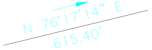
The Angle/Distance sub-menu contains many commands for labeling the angle and/or distance of line segments. The line segments can be defined by picking a line, picking a polyline segment, entering two point numbers or picking two points. The angles can be labeled in bearing, azimuth or gon format. In the command names, the "_" indicates which side of the line label will appear. For example, "Bearing_" will label the bearing above the line and "_Bearing" will label below the line. There is also a Custom Label Formatter option. When this command is used and Option is chosen, there will appear a Custom Line Label dialog with various settings.
Define bearing by, Points/type
in Bearing/<select line or polyline>: P
1st Point ?
Pick point or point number: 11
PtNo. North(y) East(x) Elev(z) Description
11 4869.06 4390.31 0.00
2nd Point ?
Pick point or point number: 2
PtNo. North(y) East(x) Elev(z) Description
2 4610.89 4078.44 0.00
Bearing_Distance
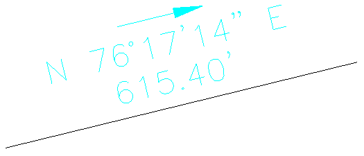
 Stacked DistanceBearing_
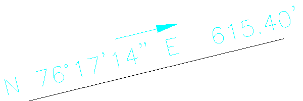
 BearingDistance_
Keyboard Command: Bearing and distance or bearing only or
distance only: brg_, bbrg, brg_dis, dis_brg, brgdis_, _brgdis,
dis_, bdis, bbrgdis; Stacked labels: stackbd, stackdb2, stackdb3,
stackdb4; Azimuth: AZI_, BAZI, AZI2_, AZI3_, azidist2, azidist3,
azidist4, dist_azi; Gon: gonlab, gonlab2, gonlab3, gonlab4.
Prerequisite: None