Surface Equipment Timing

Surface Equipment Timing schedules through distinct pits on a bench-by-bench basis. Each bench is mined by a single piece of equipment according to a working calendar. This is unique compared to the Surface Production Timing command in that it requires the use of grids/quantities stored in pits, adheres to a work calendar, and allows for varying rates of production for each piece of equipment. This command requires careful preparation and organization. The following documentation explains the details of this command according the below outline:

  1. Required Setup
  2. Surface Equipment Timing Dialog
  3. Reporting Options

1) Required Setup

Before Surface Equipment Timing may be executed, proper setup is required. This includes 1) creating pits/benches with quantities and mining direction and 2) defining the project working parameters via the Timing Project Manager.

1) Create pits/benches

In order to create pits/benches ready for timing, the following steps must be taken.

  1. Create Pits

    As previously mentioned, the Surface Equipment Timing command schedules through pits on a bench-by-bench basis. These benches are the base unit used for scheduling, making proper layout of pits/benches key to effective scheduling. It is helpful to first define the scope of the planning process (long-range vs. short-range and schedule flexibility required for equipment). It is important to note that only one piece of equipment may work on one bench at a time, and that partial mining of a bench is not allowed; once a piece of equipment begins mining a bench, it must finish that bench before it can start on another bench.

    Short range planning can require more flexibility in the sequencing of pits/benches, which requires pits/benches to be divided into smaller distinct units. Long range planning, however, often requires less detail, and can therefore consider larger areas to be mined as a single unit. Consider the below image, which shows how an area of land may be divided into pit outlines for different planning scenarios. The pits shown on the right do not allow for much flexibility in planning. If only one piece of equipment is working, at least one bench of each long pit must be fully mined before mining another bench. The pits on the left, however, allow for a greater amount of flexibility. In this scenario, a piece of equipment may mine Bench 1 of Cut 1-1, then mine Bench 1 of Cut 1-2, followed by Bench 2 of Cut 1-1, etc.


    Pits are simply closed polylines that are tagged with a pit name and additional information. To create pits from linework, one of the below commands may be used. All of these commands are found under the Boundary Pulldown Menu of the Surface Mining Module. Detailed information about each command is listed in the corresponding section of the help manual.


  2. Store Quantities/Qualities to Pits by Bench

    Once the pits have been created, the quantity and quality of material to be mined must be calculated within those boundaries. This information is stored within each pit in distinct benches. This is done by one of the below commands. The Surface Mine Reserves command is found under the Reserves/Timing Pulldown Menu, while the other two are found under the Boundary Pulldown Menu. Detailed information about each command is listed in the respective location of the help manual.


  3. Assign Mining Direction

    Before pits/benches may be scheduled, a mining direction must be assigned. Some of the pit layout tools will assign mining directions automatically. Pits without a mining direction may be assigned direction via the Assign Directions command. Mining direction may vary by bench. It is important to note that the mining direction does not control the sequencing of pits. For example, a long row of pits may be sequenced to mine the west end first and progress to the east, but mining of each individual pit does not have to progress from west to east.

  4. Optional - Verify Pits

    Once pits have been named, assigned quantities/qualities by bench, and assigned a mining direction, they may be verified that they are ready for timing via one of the following commands, all of which are found under the Boundary Pulldown Menu.

2) Timing Project Manager

Working parameters are defined in the Timing Project Manager. This includes information such as the number of working units, equipment working rates, number of shifts, working calendars, etc. Each time the Surface Equipment Timing command is executed, the current Timing Project Manger settings will be displayed before continuing. An example of the Timing Project Manager is shown below. Detailed information about this command is available here.


2) Surface Equipment Timing Dialog

Once the pits/benches and working parameters have been defined, the Surface Equipment Timing command may be used. After accepting the settings in the Timing Project Manager, the Surface Equipment Timing Dialog will appear as below.


The Equip. Involved Column lists all pieces of equipment to be used for the mine scheduling. Benches must be assigned to a specific piece of equipment in order to be mined.

Add Unit: This button will add new pieces of equipment to the list. When clicked, a list of equipment defined in the Timing Project Manager will appear as shown below. Units may be added to the list by selecting the unit and clicking OK, or by double-clicking the unit. Multiple units may be added at the same time.


Copy Unit: This button will create a copy of the currently select unit.

Edit Unit: This button will allow you to edit the specifications of the currently selected equipment. More information on defining equipment specifications is available in the Timing Project Manager section of the help manual.

Replace Unit: This button will replace the currently selected unit with another unit. When a unit is replaced, all benches and delays assigned to the original unit will be re-assigned to the new unit. This is quicker than removing bench assignments from one unit and then manually re-assigning them to the new unit.

Remove Unit: This button will remove the currently selected unit from the list. All benches and delays assigned to the unit will return to the unassigned column when the unit is removed.

Edit Calendar: This button will allow you to edit the current work calendar. More information on defining the work calendar is available in the Timing Project Manager section of the help manual.


The Assignment Column lists the benches assigned to the currently selected equipment. Selecting a different unit will update this column with the list of benches assigned to that unit. This column lists benches in the order that they will be mined, with benches at the top of the list being mined first.


Do Earlier: This button will move the currently selected bench upwards in the list, causing it to be mined earlier in the sequence.

Do Later: This button will move the currently selected bench downwards in the list, causing it to be mined later in the sequence.

Remove: This button will remove the currently selected bench from the list, allowing it to be re-assigned to another piece of equipment.

Remove All: This button will remove all assignments from the currently selected unit.

Add Delay: This button will open the dialog shown below, which controls how delays are handled. A delay will appear in the Assignment Column as if it were another bench to be mined, and may be moved up or down in the sequence.


Delay Duration: These values control how long the delay lasts. In the above example, the equipment will be delayed for a full shift. Note that partial shift delays are allowed.

Pure Calendar Delay: This option will not force a delay. If the equipment already has scheduled downtime when the delay is encountered, additional time will not be taken off.

As Scheduled Delay: This option will force a delay even if the equipment already has scheduled downtime when the delay is encountered. The delay will wait until the scheduled downtime is complete, then the delay will be applied.

Pure Calendar Delay after precedence is satisfied: This is similar to a Pure Calendar Delay, but will not attempt to apply the delay until precedence rules have been satisfied. Consider the scenario shown in the below table. Equipment E1 is scheduled to mine Pit A and Pit C. Equipment E2 is scheduled to mine Pit B and Pit D. A precedence rule has been created that does not allow Pit D to be mined until Pit A is complete. A delay of this type is placed on Equipment E2 after Pit B. In this scenario, the finish date of Pit A will first be calculated, then the delay will be applied. If the equipment already has scheduled downtime when the delay is encountered, additional time will not be taken off.

As Scheduled Delay after precedence is satisfied: This option is similar to an As Scheduled Delay, but will not attempt to apply the delay until precedence rules have been satisfied. Consider the below scenario. Equipment E1 is scheduled to mine Pit A and Pit C. Equipment E2 is scheduled to mine Pit B and Pit D. A precedence rule has been created that does not allow Pit D to be mined until Pit A is complete. A delay of this type is placed on Equipment E2 after Pit B. In this scenario, the finish date of Pit A will first be calculated, then the delay will be applied. If the equipment already has scheduled downtime, the delay will be applied in addition to this downtime.

Due To: This dropdown menu lists the Drawing Event delays defined in the Timing Project Manager. The ellipse button will allow you to define a new Drawing Event.


The Unassigned Column lists all benches that have not yet been assigned to a piece of equipment.


Assign: This button will assign the selected bench(es) to the selected piece of equipment.

Select: This button will select all benches according to the drop-down menu to the right of this button. If the drop-down menu is set to NONE, all benches will be unselected. If the drop-down menu is set to ALL, all benches will be selected. If the drop-down menu is set to Bench 1, Bench 1 from all pits in the list will be selected.

Sort: This drop-down list will sort the benches according to a variety of options.

  • Pit, Bench: this option will sort the list in order of increasing pits, then in order of increasing benches (for example Pit1-B1; Pit1-B2; Pit2-B1; Pit2-B2; etc.)
  • Bench, Pit: this option will sort the list in order of increasing bench, then in order of increasing pit number (for example Pit1-B1; Pit2-B1; Pit1-B2; Pit2-B2; etc.)
  • X-Bench Staircase: this option will sort the benches in a staircase method according to the number of benches available. A three-bench scenario will sort the benches in a staircase-fashion such as
    Pit1-B1;    Pit2-B1; Pit1-B2;    Pit3-B1; Pit2-B2; Pit1-B3;    Pit4-B1; Pit3-B2; Pit2-B3    etc.

Inv: This checkbox will invert the sorting order of the Unassigned Column.

Use Precedence: This checkbox will ensure that precedence is satisfied in the list. For example if Pit1-B1 is assigned to precede Pit1-B2, toggling this option on will reorder the list so that Pit1-B1 is listed before Pit1-B2.

Screen Pick: This button will allow you to sequence the pits by selecting them in the drawing. When activated, the Surface Equipment Timing Dialog will disappear and the drawing area will be visible. The command line will prompt you to click inside the pit to assign to the currently selected piece of equipment. Pits/benches that have already been assigned to a piece of equipment will be filled with a transparent color. Clicking inside a pit will assign the top available bench in that pit to the selected equipment. Clicking inside the pit a second time will assign the next available bench and the fill color will change to indicate that the second available bench has been assigned. Pressing ENTER after selecting the benches will return to the Surface Equipment Timing dialog. An example of the Screen Pick method of selection is shown below.


3D Pick: This button will open a new window, as shown below, to show a 3D view of the available pits and the volumes/qualities associated with them.This interactive window allows you to sequence pits in a 3D environment.


The benches shown in the 3D graphics window will be shown as flat benches by default. However, benches may be associated with elevation surfaces to show realistic dimensions via the Timing Project Manager attribute groups. More information on this feature is available in the corresponding section of the help manual.

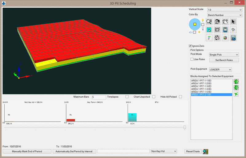
Vertical Scale: This value controls the vertical exaggeration of the graphics window.

Color By: This drop-down list controls how benches are colored in the graphics window.

The Bench Number option will color each bench level with a color specified in the Set Bench Rules options.
The Grade option will color each bench according to a grade parameter file. Any attribute in the pit may be used for grade categorization.
The Destination option will color each bench according to it's assigned destination. Note that destinations must be enabled in the Timing Project Manager in order for this option to be made available.

Control
Action
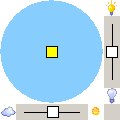
This control represents the position of the sun in plan view. If the yellow square is in the center of the blue circle, the sun is in a zenith. If the yellow square is near the edge of the circle, the sun is near the horizon. To move the yellow square, simply drag it to a new location, or click on the new location. The slider bars on the sides control the intensity and brightness of the display.
Switches to Dynamic Zoom mode. Click and drag to zoom in and out.
Switches to Rotation mode. When the cursor is placed near the outer edge of the view, a "Z" cursor is presented that permits rotation around the Z-axis. When the cursor is placed further into the interior of the view, an "X,Y" cursor is presented that permits the tilt angle of the view to be adjusted.
Switches to Pan mode. Click and drag to pan.
Switches to Pick mode. When active, double-clicking benches in the graphics window assign benches to the equipment or destination based on the Pick Action option.
Prompts you to select linework such as contours or 3D faces to add to the 3D viewer window. This linework can be used to identify reference points in the drawing to assist in pit selection.
Toggle shading of Pits and 3D Faces.
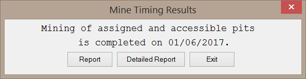
Exits the 3D Pick window, calculates the amount of time required to mine the assigned benches, and generates a report. This function is discussed later in this section of the help manual.
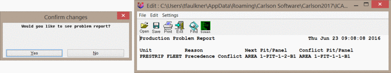
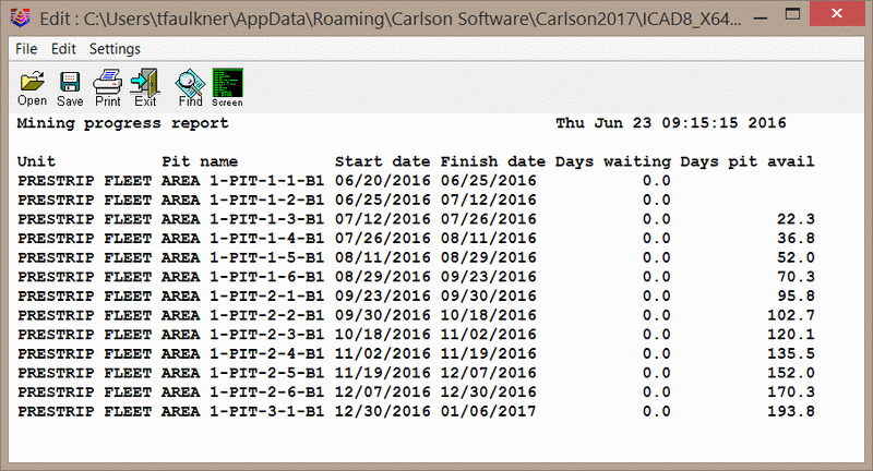
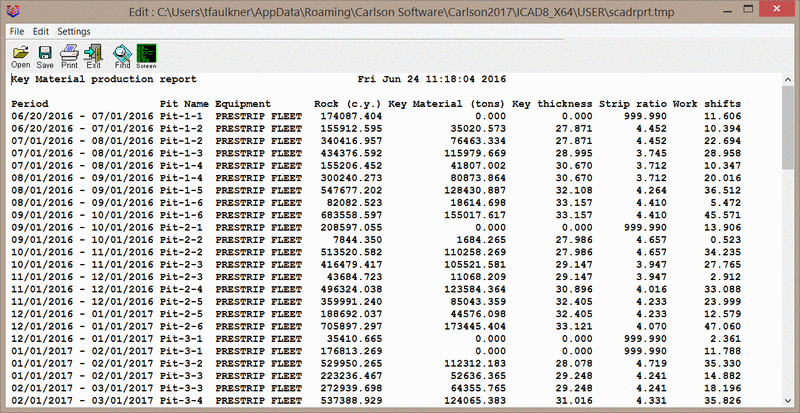
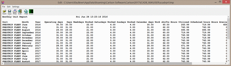
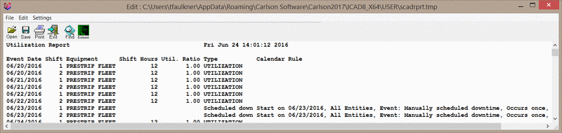
Displays a detailed report of the current timing assignment. This is similar to the standard Report function, but provides more detailed information and does not attempt to create a timing map. An example report is shown below.

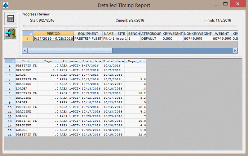
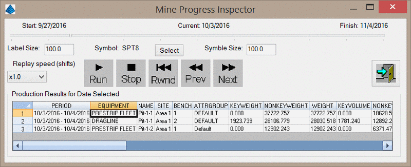
The calculator icon at the top left of the screen will recalculate the timing results of the currently assigned benches. This allows additional pits to be added/removed from the assigned equipment and then quickly recalculate the impact on the scheduling.
The slider bar at the top of dialog represents the timeline of the mining progression. Clicking-and-dragging the slider will update the displayed information.
The spreadsheet report will display benches to be mined in the currently selected time period.
Controls the information displayed on the bar charts. When clicked the below dialog will appear.

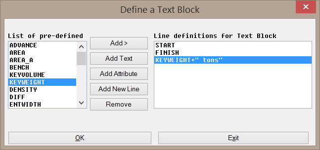
This dialog contains two columns: Available and Used. Only items in the Used column will be shown in the Quantity and Qualities chart. Items may be moved between the two columns by selecting the item and clicking one of the green arrows between the two columns. To the right of the Used column are four icons. The green arrows can be used to move the selected item up and down in the list. The green ink quill can be used to edit the selected item as described below. The blue reset icon will clear out all used attributes and return them to the available column.

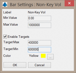
When an item is first moved to the Used column, the below dialog will appear to control that item's appearance on the chart, including minimum value to display, maximum value to display, and color. If destinations have been enabled in the pits, you will be able to define charts for each grade of material according to the grade parameter file used to color the pits by Grade.


Controls the attributes that are displayed in the tooltip when the cursor is hovering over a bench. Attributes in the left column will not be displayed. Note that some attributes such as key volume will always be shown in the tooltip.

This icon will only be shown when destinations have been enabled in the Timing Project Manager. When clicked, the below dialog will appear. Here you can define various destinations and assign a color. Destinations may be be added/removed with the plus/minus icons, and reordered with the up/down arrows.

This icon will only be shown when destinations have been enabled in the Timing Project Manager. Clicking this button will prompt you for a grade parameter file. Benches will then be automatically assigned to their various destinations based on the grade of the material. Please note that the color assigned to the grade category in the grade parameter file must match the color of a pit destination. If no match is found, the bench will be assigned to the first destination in the above list.

Ignore zero elev: This option will toggle the visibility of surface features at zero elevation in the graphics window.

Pick Mode: This drop-down list controls how benches are assigned to equipment. When the Single Pick option is selected, benches will be selected one at a time by double-clicking on each bench. When the Multi Pick option is selected, multiple pits may be assigned by double-clicking the first pit in a line to be mined, then double-clicking the last pit to be mined. Once two pits have been selected, they may be assigned to the equipment by right-clicking anywhere in the graphics window. Additional lines of pits may be added with additional double-clicks.

Use Rules: This option will apply the bench rules when selecting benches. These option can be defined with the Turn Benches On/Off icon.

Set Bench Rules: This button will open the Bench Sequencing dialog, shown below. This is intended to assist with sequencing when using the Single Pick option of selecting benches. When a bench is selected for mining, other benches will be automatically selected based on these bench rules. Note that in order to use the Bench Rules, pits must be oriented in the N-E-S-W directions. If the pits are not naturally oriented this way, the Twist Screen command may be used (prior to executing the Surface Equipment Timing command) to align the pits in the N-E-S-W directions.

The Graphics window at the top of this dialog will show an example of the bench rules to be applied.
The List of Benches on the left side of this dialog controls various options for the benches.
The Mining Rules on the right side of this dialog control the automatic sequencing of the benches.

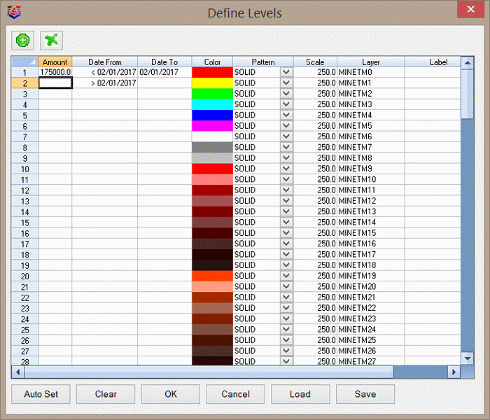
Bench Column: This column lists the benches in order from top to bottom.

Show Column: This column controls if benches are shown in the graphics window.

Color Column: This column controls the color of each bench. Double-clicking one of the color cells will open the CAD color palette for color selection.

Equipment Column: This column controls which piece of equipment the bench will be assigned to. If no equipment is specified, the benches will be assigned to the current equipment selected on the 3D pick dialog.

Upper Bench Offsets: This graphic controls how many benches should be developed in addition to the bench that is actually selected in the 3D Pick dialog. The center square represents the bench that is selected in the 3D pick window. The numbers on each side of this square control how many upper-level benches must be sequenced in addition to the selected bench. In the above image, anytime a bench on level-2 is selected for sequencing, the bench on level-1 just to the east will also be sequenced. These benches will be assigned to the equipment specified in the Equipment Column.

Upper Bench Sequence: This graphic controls actual sequencing of the automatically sequenced benches. In the above image, the upper bench (red) will be mined first, then the level 2 bench will be mined.

Set to All: This button will apply the current bench sequencing rule to all other benches. For example, if a rule is defined for level 2 to mine one bench to the east on level 1, clicking this button will apply a similar rule to lower benches.

All On: This button will enable the "Show" toggle for each bench.

All Off: This button will disable the "Show" toggle for each bench.

Draw: This button will draw a preview of the selection in CAD. Picking a bench will fill in that bench with a yellow hatch. All other benches to be automatically sequenced along with this bench will be outlined with the same Bench Color. In the below example, Pit 1-3 Bench 2 has been picked for scheduling, and Pit 1-4 Bench 1 has been outlined to show that it will be automatically sequenced.


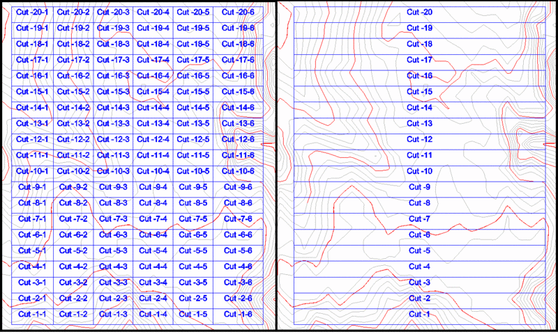
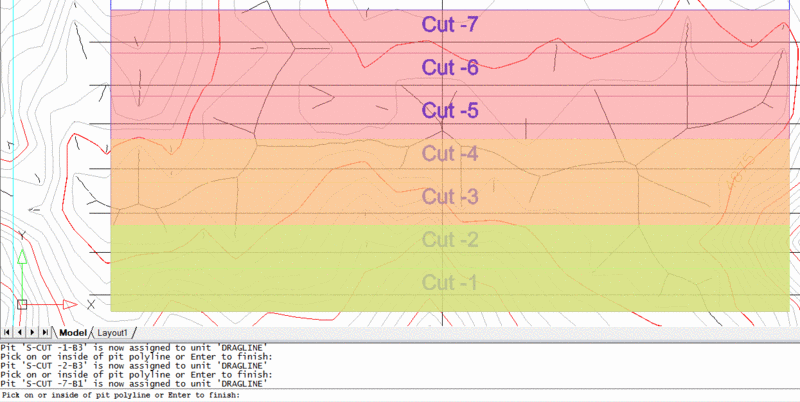
Bench Sequence Rules Example:

The below images show the bench rules for a 3-bench example. In this example, whenever a level-2 bench is selected, up to 3 level-1 benches will also be sequenced. Whenever a level-3 bench is selected, up to 3 level-2 benches will also be sequenced. These rules compound, meaning that whenever a level 3-bench is selected, up to 8 level-1 benches may also be sequenced.


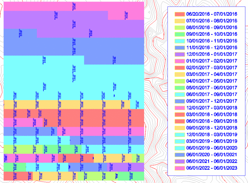
Using these bench rules, 5 benches were manually picked as shown below. The yellow number, indicating the order of selection, lies on top of the bench that was actually selected; all other benches were automatically assigned to the appropriate equipment. The final sequence applied to each piece of equipment is also shown below this progression. This allows a total of 26 benches to be sequenced by selecting only 5 benches. This can save tremendous amounts of time when working with multi-bench pits.

Pick Action: This option will only be shown when pit destinations have been enabled in the Timing Project Manager.

The Set Equipment option will assign benches to the current equipment.
The Set Destination option will assign the destination of the selected bench.

Pick Destination: This option will only be shown when pit destinations have been enabled in the Timing Project Manager and when the Pick Action is set to Set Destination. When shown, any benches selected will be assigned to the currently selected destination.

Pick Equipment: This drop-down list includes all equipment that have been added to the main Surface Equipment Timing dialog. Benches will be assigned to the selected equipment.

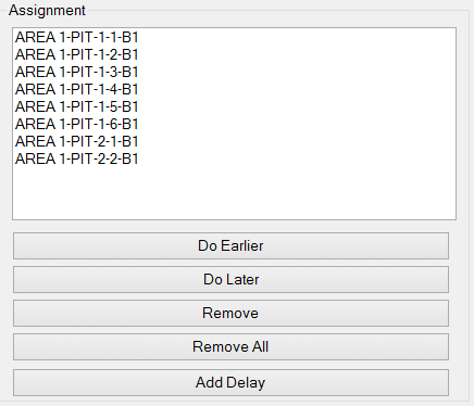
Blocks Assigned To Selected Equipment column: This list shows all benches that have been assigned to the selected equipment. The benches are listed in the order they will be mined. The green arrows to the right of this list will move the currently selected bench up and down in the list. The green X to the right of this list will remove the selected bench from the list and make it available for assignment to another piece of equipment.

Bar Charts: The charts at the bottom of the dialog show the quantities and qualities of the pits assigned to the current piece of equipment. As benches are assigned to a piece of equipment, the charts will dynamically update. The appearance of each chart is controlled with the Chart Settings icon, as discussed above. Each chart may show multiple vertical bars, with each bar representing a period of one or more pits. Periods may be defined manually or automatically. It is important to note, however, that the periods that define these charts are only temporary tools for inspection - these periods will not be used in the final timing report. It is important to note that the bar charts are intended to be a short-term inspection tool. The bar charts will not be saved when you exit the 3D Pick window.

Maximum Bars: This value controls the maximum number of periods (and thus, the number of vertical bars) that may be shown in each chart.

Timelapse: This checkbox will create a new period each time a bench is selected, thus adding another bar to the charts. Once the maximum number of periods is displayed, older periods will be removed from the charts. You will need to click the Reset Charts button before this option can be disabled.

Chart Unpicked: This option will reset the charts and only show information pertaining to benches that have not yet been assigned to a piece of equipment.

Hide All Picked: This option will not display benches that have been assigned to a piece of equipment when the slider bar is adjusted. When this option is enabled, moving the slider bar to the left will display assigned benches in the 3D viewer window, but they will be colored white to indicate that they have been assigned to a piece of equipment. Displaying the benches in this way can be useful when adjusting the slider bar to represent a specific mining period.

Period Slider Bar: The slider bar below the charts is only available when the Timelapse option is disabled. This slider bar allows you to control how many benches are represented in the last vertical bar of the charts. For example, if the slider bar is moved to the right end of the bar, all assigned pits will be represented in the last vertical bar chart. If the slider bar is moved closer further to the left, then fewer pits will be represented in the last vertical bar chart.

Manually Mark End of Period: This option is only available when the Timelapse option is disabled. The slider above this button controls which benches are in the current period. When this button is clicked, the current period will end and a new vertical bar will be added to the charts. You may then repeat the process to create additional periods. This allows you to compare attributes for multiple periods, thus showing, how the quality of the material mined will change over time. When manually marking the ends of the periods, none of the benches from a previous period will be considered in the new period.

Automatically Set Period by Interval: This button will define periods according to a set value. The pulldown menu to the right of this field controls which attribute is to be used for the definition of each period. For example, if this option is set to mark periods at 10,000 Key Ton intervals, the program will determine how many benches are needed to hit that target. Each time the value is exceeded, a new vertical bar will be added to the charts. It is often useful to reset the charts before using this option.

Reset Charts: This button will clear the charts.


Additional scheduling options are shown at the bottom of the Surface Equipment Timing dialog.

Starting Date: This value sets the date to begin mining operations. The ellipse button to the right of this field will open a small calendar to assist in date selection. By default, this value will be set the Mine Start Date set in the Timing Project Manager.

Number of Shifts: This value will set the number of working shifts in a day.

Skip COAL (Key Material) for timing: This checkbox controls if key material is used for the timing or not. When this option is on, the key material (be it coal or some other resource) will not be included in the scheduling. Instead, it will be assumed that all key material will be mined quickly enough so that it never delays the removal of waste material.

Perform Bottleneck Analysis: This option will perform a bottleneck analysis by limiting the total production from several pieces of equipment.

Bottleneck Params: This button will open the below dialog (left), which controls the Bottleneck Analysis.


The above dialog (left) lists all bottleneck parameters. The green plus icon to the left of the list will add a new parameter to analyze. The green ink quill icon will edit the selected parameter. The green minus icon will remove the selected parameter. When a new parameter is added, or a current parameter is edited, the dialog shown above (right) will open.

Field Name: This field sets the value to be used for bottleneck analysis, such as NONKEYVOLUME. This name must EXACTLY match an attribute used in the Detailed Report. A partial list of available names is given below. Note that user-defined attributes are not shown below. A full list of available attributes may be found in the Detailed Report > Report Formatter > Settings Tab > Attrib Options.

  • KEYVOLUME
  • NONKEYVOLUME
  • KEYWEIGHT
  • NONKEYWEIGHT
  • WEIGHT
  • etc.

Threshold: This value is the limit to be placed on Field Name. In the above dialog, a maximum of 10,000 cubic yards of waste may be mined in a single shift.

Unit Name: This value sets the equipment to be limited by the Field Name. In the above example, the 10,000 cubic yard threshold is applied to all units. If only one or two units are listed, then the combined production of those units may not exceed the threshold value. The order in which units are listed will is used in the Restriction Scheme option.

Restriction Scheme: This drop-down list controls how units are-scaled back due to bottlenecks.

The Normal Rotation option will alternate production through all units.
The Hold Lead, rotate rest option will operate the first unit listed in the Unit Name filed at full production and all other units will be rotated through production.
The Hold Tail, rotate rest option will operate the last unit listed in the Unit Name field at full production and all other units will be rotated through production.
The Fixed order option maintains the order of unit preference and reduces production beginning with the tail unit until it is completely idled, then the next unit in the preference order is reduced until the objective is met.

Bottleneck Example: Consider a PRESTRIP FLEET with a production capacity of 15,000 cubic yards per shift and a LOADER with a production of 12,000 cubic yards per shift. All the material excavated must be loaded and hauled away. Only 10 trucks are available to haul material, each with a hauling capacity of 1,000 cubic yards per shift. In this case, the trucks are the bottleneck in the mining process, limiting the overall production to 10,000 cubic yards per shift.

Using the Hold Last, rotate rest option for the Restriction Scheme, the PRESTRIP FLEET will be scaled back as necessary to ensure the LOADER is always operating at full capacity. When the schedule is calculated, the production capacity of each shift is checked, as indicated in the timing window shown below (left). After the schedule is checked for bottlenecks, a report of the shifts that require units to be scaled back will be generated, as shown below (right).

Perform Period Target Analysis: This option will perform a Period Target Analysis, which will add extra truck and shovel units for overburden removal as needed in order to ensure production targets are met. It is important to note that this option can only be used to increase overburden removal - additional units will not be added to increase the production rate of key material. To use this function, a piece of equipment named TRUCK&SHOVEL must be defined in the Timing Project Manager.

Target Params: This button will open the dialog shown below.


Maximum Amount of Truck and Shovel: This drop-down list will set the maximum number of Truck and Shovel units to be added to meet the production target.

Edit Range Definitions: This button will open the below dialog. In this dialog, the AMOUNT column represents the amount of Key material (in tons/tonnes) to be uncovered during the specified time period. This dialog is similar to the Amounts table, which is discussed in the Reporting Options section of this document. In the below example, a target production of 175,000 tons of key material must be uncovered by 02/01/2017.


Target Production Analysis example:
Consider the dialog shown above and the below reports. In the first report, only ~146,000 tons of coal are uncovered. This is accomplished by mining three pits to completion and partially mining a fourth pit. If the target production shown above is applied, however, truck and shovel units are used to remove additional overburden in order to uncover the targeted 175,000 tons of coal.


Allow Retreat with No Advance: This option is only used for the Underground Timing command. It will be disabled in the Surface Equipment Timing command.

Collect Extended Information for Gantt Chart: When enabled this option will allow the Gantt Chart to include extra information such as the pit volume, quality, etc.


3) Reporting Options

The bottom of the Surface Equipment Timing dialog, shown below, has several buttons for generating reports.


Calculate: This button will calculate the mine schedule. If any errors are encountered, the below dialog (left) will appear. The problem report generated will appear similar to below (right). In this example, a precedence rule has been violated for the PRESTRIP FLEET equipment. Pit-1-2-B1 cannot be mined until Pit-1-1-B1 has been mined. This will require an edit to the assignment order.


If no problems are encountered, the schedule will be calculated and the below dialog will appear.


Report: This button will generate a very simple report as shown below. Note that this report does not include information about the amount of material mined.


Detailed Report: This button will generate a more detailed report, including information such as the amount of material mined, quality of material, downtime, etc. This report is discussed in more detail later in this help document.

Progress Review: This button will open the Progress Inspector shown below. The Progress Inspector will only be generated with information after the mine schedule has been calculated.

The Progress Inspector allows you to step through the day-by-day schedule of each piece of equipment. The slider bar at the top of the window may be used to cycle through the dates quickly. Various information about each piece of equipment is shown in the spreadsheet view. As you progress through each day with the below controls, a symbol and label will appear on the drawing to indicate the location of the equipment. The size of the labels/symbols may be set with the Label Size and Symbol Size. A different symbol may be selected by clicking the Select button.

Run: This button steps through the overall mine progression day-by-day. You may modify the playback speed by changing the Replay speed option.

Stop: This button stops the action of the Run button.

Rwnd: This button returns the inspector to the first working day of the schedule.

Prev: This button steps to the previous day in the mine schedule.

Next: This button steps to the next day in the mine schedule.

Back to Project: This button will return to the Timing Project Manager window.

Report: This button is only available after calculating the mine schedule. This button will open the Detailed Report dialog. This is the same dialog that will appear after selecting the Detailed Report option after clicking the Calculate button.

Report by Period/Equipment: These two radio buttons will determine how the timing map is generated.

If the Period option is selected, the timing map will be colored by period, regardless of which equipment is working.
If the Equipment option is selected, the timing map will be colored by piece of equipment, regardless of when the mining takes place.

Report Only: This option will not create a timing map; only the mine schedule will be reported. When selected, many other options on the dialog will be ghosted out.

Draw Hatch: This option will create boundaries for the timing periods and fill them in with the specified hatch pattern.

Draw Distinct Outlines: This option will draw the boundaries of the timing periods as closed polylines.

Draw Legend: This option will draw a color legend of the timing map.

Pastel Colors: This option will use pastel colors rather than the brighter, primary colors. This is useful when plotting as the lighter colors use less ink when plotting. The pastel colors are the odd-numbered colors, starting at 11, of the CAD color palette.

Enforce Custom Colors: This option will color the timing blocks according to the Dates/Colors table, but will also allow the use of a pre-set timing report.

Change Shade Color: This dropdown list will determine how the colors of the timing map change. Note that this option is not available when the Enforce Custom Colors option is selected.

Block Labeling: This dropdown list will determine how the labels are drawn in the timing map.

The No Block Labels option will not draw labels.
The Draw Actual Dates option will label the starting and ending date of each period.
The Draw Period Names option will draw labels defined in the Custom Date Table.
The Use Custom Names option will draw labels defined in the Custom Amount Table.
The Use Custom Text Block option will draw labels according to the below dialog. When selected, the Text Block Style, Add, Edit, and Remove buttons will become available. The Text Block Style dropdown list will list all available text block labels. The Add button will create a new text block. The Edit button will edit the currently selected text block. The Remove button will remove the currently selected text block.

The left side of the above dialog contains pre-defined keys that may be used in the labels. The right side of the dialog shows how the text block label will appear.

Add: This button will add the selected attribute to the current line. Multiple attributes may be added to a single line.

Add Text: This button will add custom text to the current line. In the above example, "tons" has been added as a suffix to the KEYWEIGHT attribute.

Add Attribute: This button will add any attribute that is not defined in the pre-defined list. This attribute name must match an attribute available in the final text report.

Add New Line: This button will create a new line in the text block. In the above example, three lines have been created.

Remove: This button will remove the selected line from the text block.

Text Size: This value will set the text size of the block labels.

Text Autosize: This option will automatically size the text of the block labels.

Length-wise labels: This option will rotate the block labels in line with the mining direction of each bench. If not selected, labels will be drawn perpendicular to the mining direction.

Text Style: This option will set the text style to use for the period labels. The Select button will allow you to select one of the existing text styles.


The bottom left of the dialog contains 8 radio buttons for various types of reports.
12 months + 8 quarters + years: This option will report the mine schedule monthly for the first year, quarterly for the second and third year, and annually for any period of time beyond the third year.

Show Months of Development: This option will report the mine schedule monthly starting on the first day of the schedule. For example, if the 12th is the first day of the schedule, the periods will span from the 12th to the 11th of the following month.

Show 1st Days of Months: This option will report the mine schedule monthly starting on the first day of each month. If the first day of the schedule is not on the first of the month, that period will continue until the first day of the next month.

Show Years of Development: This option will report the mine schedule annually starting on the first day of the schedule. For example, if 6/27 is the first day of the schedule, the periods will span from 6/27 to 6/26 of the following year.

Show 1st Days of Years: This option will report the mine schedule annually starting on the first day of each year. If the first day of the schedule is not on the first of the year, that period will continue until the first day of the next year.

Show Date Range: This option will reference the Report Period and Finish Date to the right of this option. This option will set this range of dates as a single period for coloring and reporting.

Custom Date Table: This option will report the mine schedule into the time periods set in the Custom Dates table, as discussed below.

Custom Amount Table: This option will report the mine schedule into the amounts set in the Custom Amountd table, as discussed below. The dropdown list below the Amounts button can be used to set the units for the amounts in the Custom Amounts Table.

Dates/Colors: This button will open the below dialog, which controls custom coloring for the timing map.


The above dialog can be used to create custom time periods to show in the timing map. The green icons at the top of the dialog will add and delete rows of information.

Date From: This column sets the starting date of the period,

Date To: This column sets the ending date of the period. Dates may be preceded by > or < to mark indefinite time periods.

Color: This column sets the color of the time period. Double clicking one of these cells will open the CAD color palette.

Pattern: This column sets the hatch pattern for the timing blocks.

Scale: This column sets the scale of the hatch pattern.

Layer: This column sets the CAD layer on which to draw the timing block.

Label: This column sets a custom label for the timing block.

Clear: This button will clear the table of all information.

Auto Set: This button will open the below dialog, which allows for quick population of the Custom Dates table.


Starting Line: This value will set the row to begin the automatic population of the Custom Date table.

Starting Date: This is the Date From that will be used on the Starting Line. The ellipse button will open a small calendar to assist in date selection.

Hatch Scale: This value will set the hatch scale for the new time periods.

Hatch Pattern: This field will set the hatch pattern for the new time periods. The ellipse button will open the list of available hatch patterns.

Set Same Layer: This option will place all new time periods on the same layer, which is set just to the right of this checkbox. The ellipse button will open the list of existing CAD layers.

Set Colors: This option will set custom colors for the new time periods. The colors are referenced in the CAD color palette, and are numbered 1 through 255.

Color Increment: This value sets the increment of colors to use for coloring. For example, a value of 10 will increment through colors 10, 20, 30, etc.

Start Color: This value sets the color to use on the Starting Row.

Repeat: This option will determine the length of the time periods. Selecting the Every option will allow you to set a custom length for the time periods. The number of time periods to create is set below this dropdown list.

Amounts: This button will open the below dialog, which controls another method of custom coloring of the timing map.


The above dialog is very similar to the Custom Dates table previously discussed. The only difference is that the dates are replaced with the Amounts column. These values may represent one of the following values to be mined:

  • Total Tons
  • Key Material Tons
  • Waste Tons
  • Total Area
  • Mined Area
  • Total Volume
  • Key Material Volume
  • Waste Volume
  • User Grid

Auto Set: This button will open the below dialog, which is very similar to the Auto Set dialog used in the Custom Dates table, as previously discussed. This dialog differs in that amounts are specified rather than dates, and the periods cannot be defined to repeat for a specific number of times.

Skip Report Formatter: This option will skip the report formatter. Rather than customizing the format of the report, the information will be automatically sent to a text file preview.

Sub-divide by properties: This option will sub-divide the report by property owner.

Output Period Grids: This option will create a grid or TIN file of the updated surface at the end of each period. When the report is generated, the below dialog will appear.


The surfaces in the above dialog will be automatically set according to the files found in the Attribute groups of the Timing Project Manager. If these surfaces have not been assigned in the Timing Project Manager, they will need to be manually selected. It is important to note that the output surfaces will display near-vertical highwalls when the mining face advances

Output Directory: This button will set the folder in which to save the output surfaces.

Output Grid Prefix: This button will set the prefix for each surface file to be saved.

Surface Grid: This surface file defines the existing surface topography.

Bottom Grid: This surface file defines the ultimate pit floor.

Bench# _: Each of these surfaces define the bottom of each bench.

Output Spatial Database: This option will output the report information to an SQLITE database. The database will retain the coordinate system of the drawing for linkage with GIS software packages.

Period Polylines to Pits: This option will generate new Carlson pits from the period boundaries. The pit names will match the name of the period used to create them.

Output Spoil File: This option will create a .spo file to be used with the spoil timing commands found under the Spoil Pulldown Menu. The .spo file includes the amount of waste material excavated from each pit, the date the pit was excavated, etc.

Legend Scale: This option will set the text size of the timing map legend. 

Hatch: This dropdown list will set the hatch pattern used to fill the timing blocks.

Retreat Hatch: This option is only available in the Underground Timing command.

Scale: This option sets the scale of the hatch patterns used for each timing period.

Transparency: This dropdown list will determine the transparency of the hatch pattern of each timing period. 

Layer: This field sets the CAD layer for the linework of the timing map. The Select button to the right of this field will allow you to select an existing CAD layer. 

Layers by year: This option will place linework from each year on a unique layer. The year will be the suffix to the layer name.

Layers by period: This option will place linework from each period on a unique layer.

Stop at last period: This option is only available when the Custom Amount Table report option is selected. This option will end the schedule at the last entered user row in the Custom Amount Table. 

Split report by strata fraction: This option will utilize the tonnage and volume factors stored as pit attributes and report out the volume and tons of each named strata (rather than simply reporting Key and Non-key values).

Examples of a timing map and a generated text report are shown below. Note that there are MANY ways that a timing map and report may be formatted.


There are many attributes available in this report. Most of these attributes are self explanatory, but some are not as clear. The below definitions are therefore provided.
  • Difficulty Factor: This mining rate factor represents the difficulty of mining a specific area. A value of 1.0 means that mining progresses at a normal rate. This value is the product of the Equipment Difficulty and the Location Difficulty.
  • Equipment Difficulty: This value is the product of the optional difficulty rates set in the equipment definitions. This can include
    • Date Difficulty
    • Thickness Difficulty
    • Bench Difficulty
  • Location Difficulty: This value is a difficulty factor determined by a hierarchy of the following three options. If the high priority item is detected, it will be used instead of the other two options. If the high priority option is not detected, the medium priority item will be used. If neither of these items are detected, the low priority item will be used. The low priority item defaults to a value of 1.0, so if no location difficulty is defined, the mining rate will not be affected.
    • Highest priority: text in the drawing on the DIFFICULTY layer
    • Medium priority: DIFFICULTY attribute value/grid in the Timing Project Manager Attribute Groups
    • Lowest priority: Difficulty value assigned to the specific pit (set with the EDITPIT command)
  • Calendar Days: Actual period length rounded up (to account for partial days)
  • Operating days: Actual period length rounded up, minus days that do not have at least one working shift
  • Days: Scheduled Hours divided by Shift Length
  • Weekdays Worked: Weekdays with at least a portion of shift worked
  • Saturdays Worked: Saturdays with a least a portion of a shift worked
  • Sundays Worked: Sundays with a least a portion of a shift worked
  • Days Waiting: Number of days equipment cannot work due to a precedence rule
  • Work Shifts: Number of shifts when production took place
  • Hours Scheduled: Number of hours equipment is scheduled to work (this includes Hours Utilized, Hours Delayed, and Hours Available)
  • Hours Down: Number of hours equipment is not scheduled to work (due to downtime scheduled on the calendar)
  • Hours Utilized: Number of hours equipment is actually working
  • Hours Delayed: Number of hours equipment is delayed due to a Drawing Event or Scheduled Delay (note, this is not the same as Hours Down)
  • Hours Available: Number of hours is scheduled to work, but is neither being utilized nor is it actually delayed. If a piece of equipment encounters a delay during the middle of the shift, the partial shift time remaining will be counted as Hours Available (the delay will be applied to the next shift)
   
    The below image helps visualize the organization of the different definitions of Hours.

Undo Report: This button will delete a previous timing map and clear the calculated schedule. This allows for quick what-if analysis of the scheduling.

Events Report: This button will display the Events Report, which lists all Drawing Events encountered during the mine schedule. Drawing Events are discussed in more detail in the Timing Project Manager. This report is only available after a Detailed Report has been generated. An example of the Events Report is shown below, in which four drawing events were encountered.

Monthly Report: This button will generate a monthly report, similar to the Detailed Report, but with less information available and without the ability to set custom time periods for reporting. An example of the Monthly Report is shown below.


Gantt Chart: This button will generate a Gantt chart of the mine schedule. This button is only available after calculating the mine schedule. For more information, see the Gantt Chart section of the help manual.

Utilization Report: This button will generate a Utilization Report of the mine schedule. This report lists each shift for each piece of equipment. Scheduled delays will be reported as such. An example of the Utilization Report is shown below.


Prompts
Select all pit polylines.
Select objects:
Pick all polylines Pull-Down Menu Location: Reserves/Timing
Keyboard Command:
timepit
Related Commands:
Surface Mine Reserves, Assign Directions, Surface Project Manager, Assign Timing Grids, Import Timing Data, Define Pit Attributes