Assign Template Point Profile
This command assigns profile (.PRO) files to template point ID's
like EP (edge of pavement), SH (shoulder) or DL (ditch line),
storing this information in a template point profile (.TPP) file
which can be used by the Process Road Design and
Road Network
commands. The purpose of the profile assignments is to allow
separate profiles for template points that are independent of the
centerline profile. For example, a ditch grade could have a
different profile than the centerline. Multiple template point
profiles can be assigned so the amount of control is unlimited. The
Template Point Description corresponds to the name set in the
Design Template command.
If you want the template ID point to follow a special slope or
vertical alignment, use Assign Template Point Profile. The
combination of using template point centerlines and profiles
applied to particular template ID points is a design method
sometimes referred to as "strings", where template elements string
along special horizontal and vertical alignments. The rules of the
template in terms of distances and slopes to the next point in the
template will resume after the template point centerline and
profiles are applied.
Prompts
First you are prompted to create a new Template Point Profile
(.TPP), or edit an existing one.
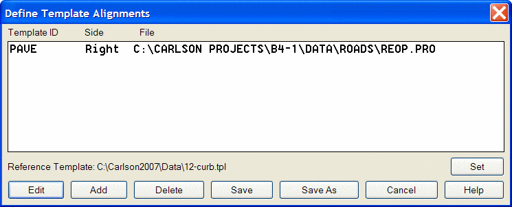
Next the Define Template Alignments dialog is presented, showing a
list of existing Template ID-Profile assignments. To add a new
assignment, first pick the Set button to set the Reference Template
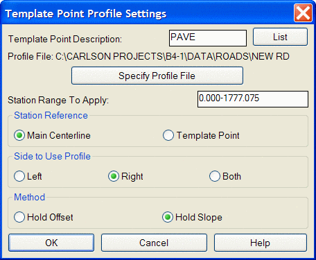
file (.TPL), then pick the Add button. This brings up the Template
Point Profile Settings dialog. First, pick a Template Point
Description from the List, which is derived from the components
defined in the Template. Next, pick the Specify Profile File
button, to choose the file (.PRO) to assign to the Template Point
ID. Alternatively, instead of picking a profile, you can use the
Screen Pick button to select a 3D polyline from the drawing which
the program will use to generate a profile. Next, enter the Station
range to Apply the assignment. The Station Reference sets whether
the template profile stationing uses the same stationing as the
main CL or uses the. template grade stationing. The template grade
stationing applies when the template grade is also using a Template
Point Centerline so that the template grade has a different length
than the main CL. The Side To Use Profile specifies if this profile
is for the Left, Right, or both sides of the main centerline. The
Method setting controls how to apply the profile. Since the
template profile can change the relative position of the template
ID from the centerline, you have two options for how to fit in the
template ID profile: Hold Offset or Hold Slope. Hold Offset will
keep the same offset for the template ID and adjust the slope to
the template ID. The Hold Slope will keep the same slope to the
template ID and adjust the offset to reach the template ID profile
elevation. Use Hold Offset when Template Point Profile is used in
conjunction with Template Point Centerline, where a single template
ID is defined to follow both a special and distinct horizontal
alignment (centerline) and vertical alignment (profile).
Pick OK. Back in the Define Template Alignments dialog, pick
Add to add another assignment, Edit to edit an existing assignment,
Report to create a report of the template point profile data,
Delete to delete a defined assignment, or Save to Exit.
Now Process the road design employing the newly defined Template
Point Profile assignment. In the Process Road Design main dialog,
pick the Template Point Profile button to select the new file
(.TPP). You could also create a new Template Point Profile file
directly from this dialog box by picking the Edit button and
specifying a new file name.
Pulldown Menu Location: Roads
Keyboard Command: tppset
Prerequisite: Profile file (.PRO) or 3D
polyline