Two Grid Surface Volumes calculates the cut and fill volumes between two surfaces modeled by grid (.GRD) files. These two grid files must have the same location and resolution. To create the grid files, use the Make 3D Grid File routine. When creating the second grid file, choose Use position of another file and select the first grid file. Using the position of the first grid file sets the location and resolution of second grid to match the first.
There are several other routines that calculate volumes based on grid files. Grid based volumes can be calculated by One Grid Surface Volumes, Volumes by Layer, Stockpile Volumes, and Pond/Pit Volumes. These routines have special prompting and calculate the grid surfaces and volume in one step.
Volumes by Two Surface Volumes has three steps:
1. Creating the first grid file with Make 3D Grid
File
2. Creating the second grid file with Make 3D Grid File
3. Running Two Grid Surface
Volumes
One advantage to this command is that you have more output options to help analyze volumes.
Besides grid based volumes, volumes can also be calculated between triangulation surfaces using the Volumes by Triangulation commands. Cross section end area is another volume method that is used by the Calculate Sections Volume command in the Civil Design module.
There are also options to specify inclusion and exclusion areas. When inclusion areas are specified, only the volume within this inclusion area is calculated. Important: Whenever possible you should use a polyline that represents the limits of disturbed area as the inclusion perimeter. Volumes within an exclusion area are not included in the calculations. Inclusion and exclusion areas are represented by closed polylines and must be drawn prior to calling this routine.
If the grid contains grid cells that have no elevations, you
have the option to extrapolate elevations from the grid cells with
elevations. When you choose not to extrapolate, no volume is
calculated for the grid cells left without elevations. In general,
extrapolation is not very accurate and should be avoided whenever
possible. Sometimes you may get small amounts of cut in stockpiles
that should only be fill, or small amounts of fill in pits that
should only be cut. These extraneous quantities are due to
extrapolation at the border and should be small enough to be
ignored. When inclusion or exclusion polylines are used, the
program will automatically extrapolate the grids. In addition to
writing a volume report to the file, printer or screen, there are
several volume report options.
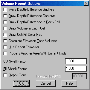
Write Difference Grid File creates a grid (.GRD) file of the elevation difference of the two grid files.
Draw Difference Contours creates a contour map of the difference or depth between the two grid files.
Draw Elevation Difference in Each Cell plots the elevation difference at the grid corners which is the same as the Elevation Difference routine.
Draw Volume in Each Cell plots the calculated volume for each grid cell and is an excellent way to verify the volume calculation. If a cell contains both cut and fill, both values will be plotted.
Calculate Elevation Zone Volumes calculates the cut and fill between different elevation ranges.
Draw Cut/Fill Color Map fills each grid cell with different shades based on the average cut or fill in the cell. Red shades are used for cut and blue for fill. There is an option to draw a color legend. You can subdivide the grid cells at zone transitions. Also, there is an option to control the zone intervals and range.
Use Report Formatter allows you to customize the report by choosing the fields to report and their order. Also the report formatter can be used to output the report data to Microsoft® Excel or Microsoft® Access.
Process Another Area with Current Grids runs Two Surface Volumes again using the same grid files but different inclusion/exclusion polylines. This option saves the step of reloading the grid files to calculate volumes from the same grids for multiple areas.
The Cut Swell Factor value is multiplied by the cut volume in the report.
The Fill Swell Factor value is multiplied by the fill volume in the report.
Report Tons allows you to enter the material density and the program will report the cut and fill tons in addition to volume.
Given two accurate grid (.GRD) files, this routine will calculate accurate volumes. To verify the volume calculation, it is a good idea to check the grid (.GRD) files either by drawing them with Draw Surface >> Draw 3D Grid File and viewing them with the 3D Vieweror by contouring the grids with the Contour Grid File command.
|
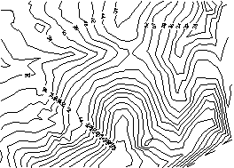
| Existing surface |
|
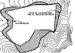
| Final surface contours with a closed polyline |
|
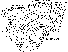
| Contours from the Draw Depth/Difference Contours option. Cut contours are red, fill contours are blue, daylight contours are green. This is a good way to check that both surfaces are modeled correctly and to verify the volumes. |
Volume Report


Comparing Grid: C:\scad2006\data\simo.grd

and Grid: C:\scad2006\data\final.grd

Lower left grid corner : 186551.67,57624.98

Upper right grid corner: 186828.81,57897.09

X grid resolution: 75, Y grid resolution: 75

X grid cell size: 3.70, Y grid cell size: 3.63

Total inclusion area: 37016.71 sq ft, 0.850 acres

Cut to Fill ratio: 1.14

Cut (C.Y) / Area (acres): 3642.35

Fill (C.Y) / Area (acres): 3182.70

Cut vol: 83570.89 cubic ft, 3095.22 cubic yards

Fill vol: 73024.56 cubic ft, 2704.61 cubic yards
Select the Inclusion perimeter polylines or ENTER for
none:
Select objects: pick a closed polyline for the limits of
disturbed area
Select objects: press Enter
Select the Exclusion perimeter polylines or ENTER for none:
Select objects: press Enter
Specify Base Grid File Selection Dialog
Choose a grid (.GRD) file to process.
Extrapolate grid to full grid size (Yes/<No>)?
press Enter If you enter Yes to this prompt, surface elevations
will be computed for any grid cells that have null
elevations.
Sample report from the Calculate Elevation Zone Volumes
option:
(Calculates the cut and fill in different elevation ranges at a
user-specified interval and beginning at a user-specified starting
elevation.)
Volumes by elevation zone
Zone 20.00 to 30.00

Cut volume : 0.30 cubic ft, 0.01 cubic yards

Fill volume: 107.90 cubic ft, 4.00 cubic yards

Zone 30.00 to 40.00

Cut volume : 4.88 cubic ft, 0.18 cubic yards

Fill volume: 73021.14 cubic ft, 2704.49 cubic yards

Running total:

Cut volume : 5.18 cubic ft, 0.19 cubic yards

Fill volume: 73129.05 cubic ft, 2708.48 cubic yards

Zone 40.00 to 50.00

Cut volume : 65044.26 cubic ft, 2409.05 cubic yards

Fill volume: 0.25 cubic ft, 0.01 cubic yards

Running total:

Cut volume : 65049.44 cubic ft, 2409.24 cubic yards

Fill volume: 73129.29 cubic ft, 2708.49 cubic yards

Zone 50.00 to 60.00

Cut volume : 17786.85 cubic ft, 658.77 cubic yards

Fill volume: 0.00 cubic ft, 0.00 cubic yards

Running total:

Cut volume : 82836.29 cubic ft, 3068.01 cubic yards
Specify Final Grid File Selection Dialog
Choose a grid (.GRD) file to process.
Extrapolate grid to full grid size (Yes/<No>)?
press Enter
Volume Report Options dialog
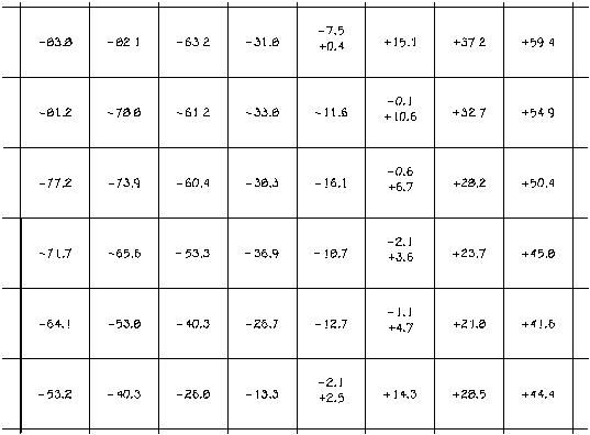
This shows a grid drawn by Plot 3D Grid File and volume values drawn by the Draw Volume in Each Cell option of the Two Surface Volumes routine. Cut appears as negative and fill as positive. Notice that cells bordering cut and fill regions contain a little of both.
Pulldown Menu Location: Surface >> Volumes By Grid
Surfaces
Keyboard Command: volcalc2
Prerequisite: Two grid files