Cut/Fill Slope Color Map
This command creates color map like the Cut/Fill Color Map routine
except instead of coloring by the amount of depth, this map uses
different colors based on the amount of slope of the design
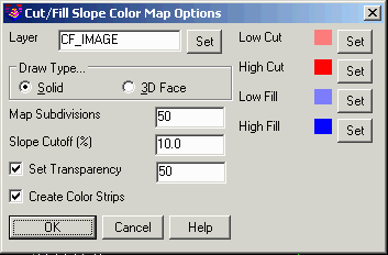
surface. In the options, the Slope Cutoff sets the slope amount for
using the specified low and high colors. Areas of cut that have a
design surface slope below the cutoff are drawn with the Low Cut
color and areas of cut over use the High Cut color. Likewise, areas
of fill with a design surface slope below the cutoff use the Low
Fill color and areas of fill over use the High Fill color.
The options dialog has settings for the color map properties
including layer, entity type and transparency. The Map Subdivisions
controls the resolution of the color map cells. A higher number
makes more cells for higher resolution. The Create Color Strips
option combines neighboring cells with the same color which speeds
up the routine and makes for a smaller dwg size.
Prompts
For a color map showing differences between two grids:
Type of surface model source [Tin/<Grid>]? press
T for a Triangulation (.TIN) file, or press Enter
to accept default choice in brackets.
Select Base Triangulation File Dialog
Select Design Triangulation File Dialog
Select Inclusion polyline: pick a closed inclusion
perimeter
Select Exclusion
polylines (Enter for none).
Select objects: pick exclusion
polylines or press Enter
Cut/Fill Color Slope Map
Options Dialog
Pulldown Menu Location: Surface > Cut/Fill
Utilities
Keyboard Command: cf_slope_map
Prerequisite: Two triangulation surfaces