Carlson Point Cloud: Step-by-Step
Tutorial Setup
This is an introductory tutorial for Carlson Point Clouds. If
you wish to follow along with the tutorial by using the same Scan
files, you can download them from the Carlson website at http://update.carlsonsw.com/tutorials/Carlson_Office.laz
You can also follow along with any other scans that have proper
target points and control points.
Launch Point Cloud Manager
Work done in Carlson's Point Cloud module is done on a
per-project basis. To create a new project, you must first have a
CAD drawing open in AutoCAD or IntelliCAD. To enable Point Clouds,
on the top toolbar click Settings => Carlson Menus
and select Point Clouds Menu. This will display the Point
Clouds menu on the top toolbar. Click on Point Clouds and
then select Project Manager.
Alternatively, on the top toolbar click Settings and select
Toolbar Setup. In the Select Toolbars window, ensure
the PointCloud option is checked. This will now display the
Lightning Bolt icon on the toolbar. Click the Lightning
Bolt icon to launch Point Cloud Manager.

Project Setup
To create a new project, in the Point Cloud Advanced window,
click New. In the New PointCloud Project window, select the
file location to save the new project, enter in a File Name and
then click on Save.
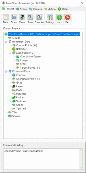
Your initial project should look like the following image. In
the tree structure you will see your Project with various
defaults.
The program will attempt a recovery in the case of an error, but it
is still recommended to Save often using the Save button at
the top of the Project Tab.
For more information see the PointCloud Project
Manager entry.
Cloud Import
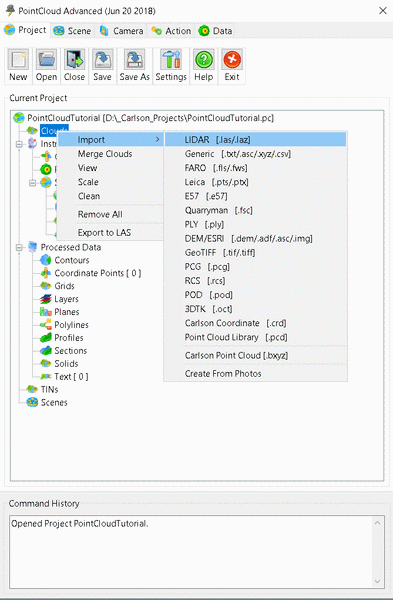
Let's begin by importing a Point Cloud. From the Project tree,
right click on Clouds ⇒ Import ⇒ LIDAR.
Find and select the TutorialData.laz file, or use any other .las
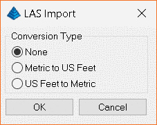
or .laz file. The program will ask if you want to convert
units. This data is in feet, so if you want to work in
Metric, select the third option. Otherwise leave this as
"None" and click OK.
A new Cloud will now be displayed in the Project Tree.
For more information see
Import Cloud.
Clean Cloud
Many clouds which are imported directly from a laser scanner or
exported from the manufacturer's software contain unnecessary
points which can be removed.
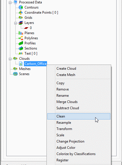
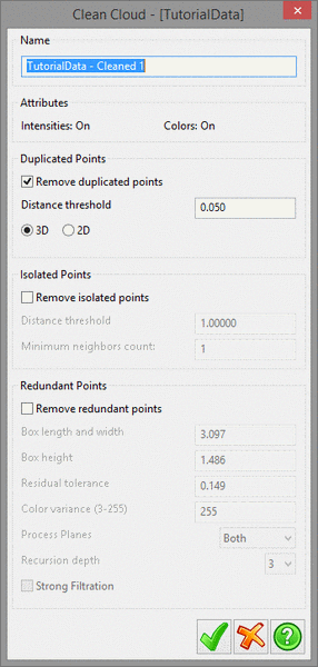
Right-click on the newly-imported Cloud and select
Clean.
For this type of scan, there are more points than necessary close
to the scanner, so we remove them via the "Remove Duplicated
Points" method.
For this Cloud, we want to make sure that the "Remove Isolated
Points" method is not enabled. Click the Green Tick to run
the Clean operation.
For more information see
Clean Cloud.
View Cloud
A new "Cleaned" Point Cloud will be availabe in the Project
Tree. Double-click on the new Cloud or right-click and go to
View.
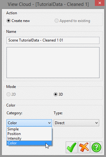
This Cloud has color in it so we will choose Color category:
Color and Type: Direct for our color mode. If this
viewing mode is not available it may indicate that the Cloud does
not have color in it.
Click on the Green Tick to open the View
window.
For more information, see Scenes.
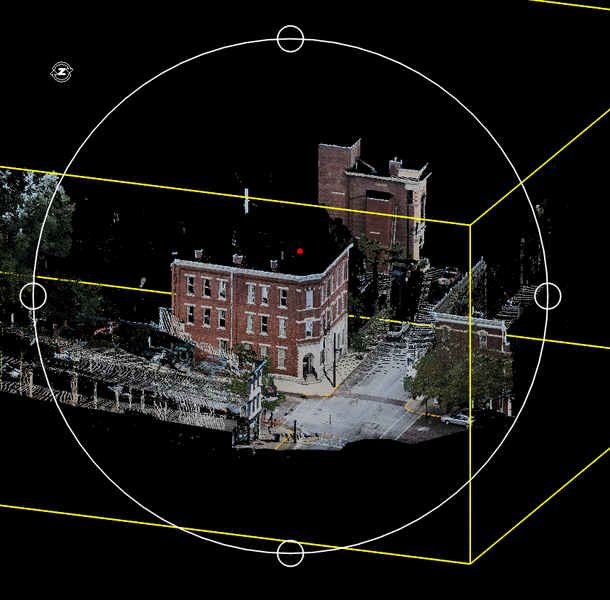
For this screenshot, the Orbit has been displayed (via the Viewer
Settings section of the
Project Settings Manager).
By default, a left-click-and-drag within the bounds of the Orbit
will change the y-angle of the scene, relative to the red pivot
point.
A left-click-and-drag outside of the Orbit will rotate the scene
relative to the z-axis and the pivot point.
A middle-click-and drag will pan the scene.
The mouse scrollwheel can be used to zoom in and out.
Virtual Survey
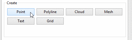
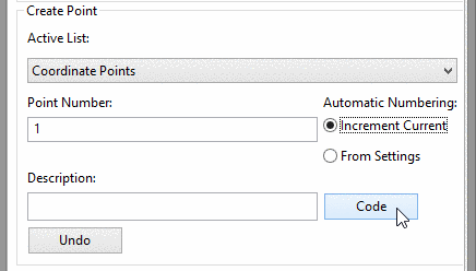
To enter the Create Point mode, select Point under
Create on the Action tab of the Project
Manager.
PointCloud will read your current .fld Code Table into a dialog
which allows you to graphically select the code to apply to the
next point.
This dialog can be accessed via the Code button.
If the Code Table dialog is empty you may need to select a
FLD File. To select a FLD File, click the Code button. In
the PointCloud - Code Table window, click the Pick FLD
File button at the top of the dialog then navigate to your FLD
file and click Open to populate the data.
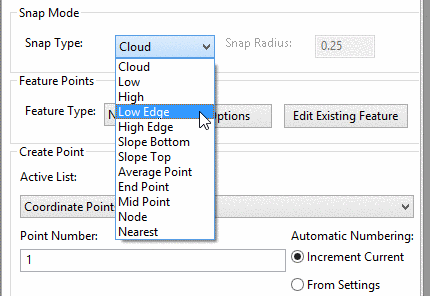
You can change the Snap Mode depending on what you are attempting
to shoot a point of. In this example we will select the
Low Edge snap type in order to create some points for the
bottom of the curb. The Snap Radius should be changed from
0.25 to 0.5 feet (if you are using meters, use a Snap Radius of
0.15 instead).
The code to use for this will vary depending on your code table,
but it is important to pay attention to the Entity Type, as this
controls whether a selected point shows up as an isolated point or
as part of a polyline.
When the red pick dot appears at the bottom of the curb, hold down
the Ctrl key and click the left mouse button to create a
point. The program will automatically label this point as the
start of the line and subsequent points with the same code
continuing the line, until you end the line with End
Linework or Ctrl-E.
Sending to CAD
After you are done with the Virtual Survey you may want to add
the created points to your current CAD drawing.
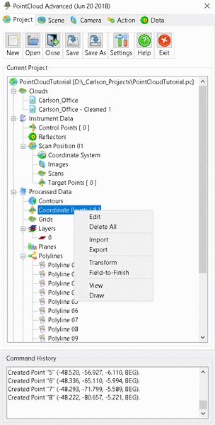
Return to the Project tab and select the entry for
Coordinate Points from Processed Data.
To edit the points or view their coordinates you can right-click
and select Edit, or double-click to open the editor window.
Right-clicking gives a few more options:
Field-to-Finish will use your Carlson F2F settings for
styles and colors when sending to CAD.
Draw will simply send the points to CAD as points, based on
the settings of the chosen Layer.
For more information see
Coordinate Points.
Mesh Creation
TIN files work best with about 1,000,000 or less points, and in
most cases where they are used, this is more than enough points to
be useful. So it can be helpful to reduce the number of
points in a Cloud before creating a TIN.
First, right-click on the already-cleaned Cloud file in the Project
Tree and click Properties.
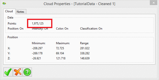
Here you can see the number of points in the current Cloud so you
know how many need to be removed. Click the Green Tick to
exit the Properties window.
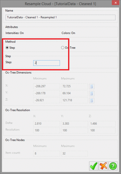
Right-click on the Cloud again and select Resample. We are
using a step size of 2 because we have approximately 2 million
points, and having already Cleaned the Cloud we assume the density
is relatively even.
Click on the Green Tick to run the Resample operation.
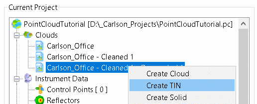
Now that we have created a more manageable Cloud, we are ready to
create a TIN. Right-click on the Resampled Cloud in the Project
Tree and select Create TIN.
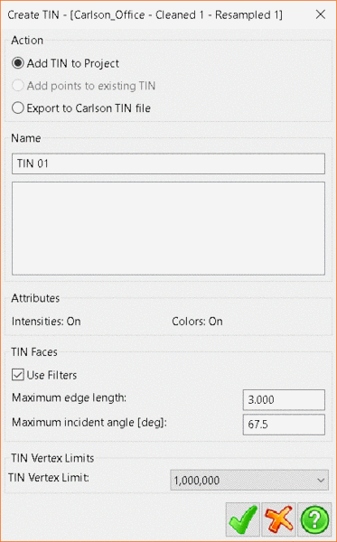
The maximum edge length should be a few times longer than the
normal distance between points in your Cloud. The incident
angle controls how tilted a triangle in the TIN can be relative to
the Normal. In this Cloud, setting this below 90 will cut off
the sides of buildings.
Click the Green Tick to create the TIN. You can also
choose to Export the TIN at this stage.
The newly-created TIN can be used in other functions which work on
triangulated data.
This completes the tutorial, but this is only as small sample of
the functionality available in Carlson PointCloud.
If you would like further assistance, please contact
support@carlsonsw.com.