PointCloud has an automatic breakline extracting function to
help facilitate the processing of a dataset.
Breakline extraction is available by clicking the
Breaklines button under the Extract panel in the
Action tab.
In order to extract breaklines, a TIN must be open in a Scene
and a user should first select the area from which to extract the
breaklines using a Selection button.
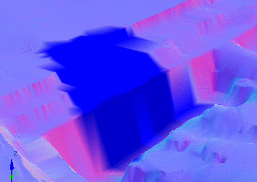
Note: For best results, it is recommended to view the TIN in a
Scene using the Color settings of Category: Position
and Type: Normal.
Click the Breaklines button a new panel should be displayed at the bottom of the Action Page which displays all the options for configuring PointCloud's breakline extraction utility. Additionally, the viewer window will remove the coloring of the current selection to prevent it from interfering with the zone flag specification process, the viewer still internally keeps track of the area of the mesh that you have selected.
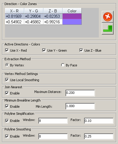
To add color zones, Ctrl + Click in the 3d view window on the mesh at a location that has the color/normal you want to define your zone. This will add the color to the Color Zones table, and you can manually modify the value if it isn't quite what you want it to be. You can choose which directions you want to be considered when zone classification is being performed using the Use X, Use Y, and Use Z check boxes. Restricting directions can yield better results in certain situations. For instance, if you're trying to extract edges along a curb, it would be best to turn off Use X and Use Y and only use the Z direction of the normal to determine the zone, due to the fact that curbs are usually a corner with a vertical surface and a horizontal surface.
There are two methods of breakline extraction: By Vertex
and By Face.
Note: This method is the default method and generally gives
better results in datasets that have hard edges (such as corners of
buildings).
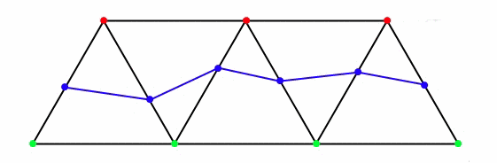
In this method, each vertex of the current selection is assigned
a zone based on the normal at that vertex. PointCloud then creates
new polyline vertices on each edge that connects vertices belonging
to different zones.
These polyline vertices are positioned based on how the vertex
normal's compare to the normal that defines its zone.
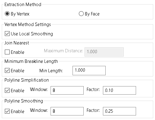
The Vertex method has one unique setting, Use Local Smoothing, which averages the normal at each vertex with the normals of its neighbors to provide a smoother set of normals to work with. This helps to give more continuous breakline edges by accommodating for places in the mesh that may be distorted due to missing or outlying data.
To extract breaklines using the Face Method, select the By
Face radio button under the Extraction Method
panel.
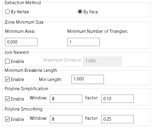
In this method, each face of the current selection is assigned a zone based on its normal. Polylines are created from the edges that touch faces belonging to a different zone. The face method has unique options of minimum area and triangle count values for each zone area. This is to prevent a common problem where a single or a small number of faces near the border will be classified as belonging to a zone other than the one they currently reside in, creating an extremely small zone.
The Join Nearest option will join any polylines whose endpoints are within the threshold distance of each other. This can help to bridge gaps in the mesh that could arise from parts of a scan being in shadow.
The Polyline Simplification option will remove each vertex that is within a certain distance to the least squares approximation. Window is the number of neighbor vertices to use when generating the least squares approximation. Threshold is a positive number that determines the distance under which vertices will be removed from the polyline.
The Polyline Smoothing option will smooth each vertex in the polyline using a least squares approximation. Window is the number of neighbor vertices to use when generating the least squares approximation. Factor is a number between 0.0 and 1.0, 0 being no smoothing performed and 1 being fitting each vertex to it's respective least squares line (usually makes the polyline extremely linear given a window size greater than 8).
Pressing the Show button at the top of the Breakline
Extraction page will only show the zones in the viewer given
the current configuration, but will not create the polyline at this
stage. Show
This gives you a chance to review your settings and make sure that
the zones are configured properly without adding any extra objects
to the project.
Pressing Extract will extract the breaklines with the given settings. Each breakline polyline will be added to the project with the a name generated from the current project settings.
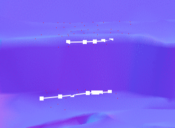
Specify Zone Flag Position Ctrl-Click in the viewer to select the color zone for breakline extraction
Tab Location(s): Action Tab
Panel and Button: Extract and Breaklines
Prerequisite: Open scene of a mesh with color by
Normal