This feature serves as an expanded version of the Layer Manager
and also as a layer standards manager. In addition to allowing you
to sort layers into easily recognizable groups called Layer
Categories, this feature can also be used to import layers
from a text file and to compare and match layers in the library to
the current drawing.
Once populated, layers from the Library can be called from commands
such as 2D Polyline and 3D
Polyline for layer and property assignment.
The Layer Library has two areas of the dialog
box: the Layer Category List on the left and the
Layer List on the right.
Layer Categories: Layer Categories are shown as
a list in a tree view in the left-hand pane of the dialog box.
Categories can be re-ordered by dragging and dropping to a
different position in the list or by using the Move
Up, Move Down, Move Left
and Move Right arrow buttons. Other buttons above
the Layer Category list also enable you to Add,
Remove and Rename Categories.
Also, right-clicking on a Category in the list displays a shortcut
menu allowing you to access many of the same commands as the
buttons along the top and bottom of the dialog box.
Layers: Layers in a
selected Category are shown as a list in spreadsheet view in the
right-hand pane of the dialog box.
Layer Properties: Except for Non-Surface, all the layer
properties in Layer Library correspond to the layer properties in
CAD. The Non-Surface property is a specific flag used by the
Triangulate & Contour routine to filter out entities. You can
set a layer as Non-Surface when you want to exclude all entities on
that layer from surface modeling.
The default column-headings for the Layer List are Name,
Description, Color, Line Type, Line Weight, Non-Surface,
Transparency, Plot Style and Plot/No Plot. Additional
column-headings may be added using the Extra Fields button at the
bottom of the dialog. Using the Add Layer (plus)
and Delete Layer (minus) buttons, layers can be
easily added and removed from a particular Category. The
Move To button can also be used to change a layer
to a different Category.
Clear All: This button
removes all the Layer Category and Layer definitions.
Save As and Load: These buttons can be used to
create and restore Layer Library settings using a
Layer Library Settings (.LA) file. There are a few default .LA
files in the Carlson Projects\Settings folder that you can load for
National CAD Standard (NCS) layers and MassDOT standard layers. The
current layer library definitions are stored in the USER folder in
a file named layerstd.dta.
Extra Fields: This button allows you to define up to ten extra text fields (column headings) for a layer. These fields can then be used as import fields or displayed in a report.
Report: This button uses
the Report Formatter to allow you to compile and display a report
containing all Layer Categories and Layers in the Library. The
Report Formatter can also be used to export the data to a Microsoft
Excel (.XLS or .XLSX) file.
Import: This button
gives you two options for Importing layers into the Layer
Library.
 The Drawing Layers
option simply copies all layer definitions from the current drawing
into the Library after prompting you to select the destination
Category.
The Drawing Layers
option simply copies all layer definitions from the current drawing
into the Library after prompting you to select the destination
Category.
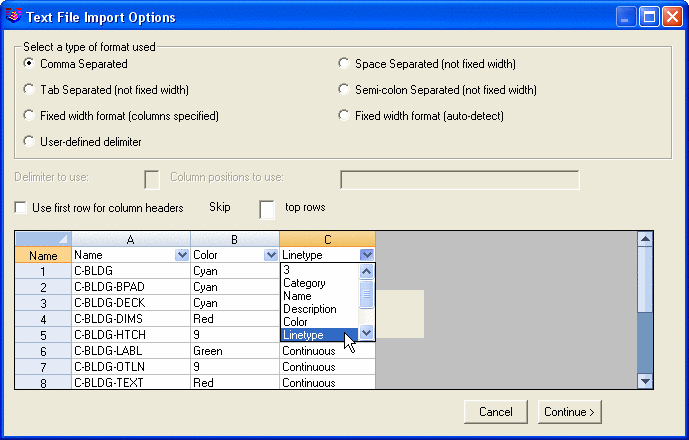
The Text File option allows you to select an
existing Text (.TXT, .DAT, or .CSV) file containing standard layer
definitions to populate the Library. Note that Microsoft Excel
provides an option to save an Excel (.XLS or .XLSX) file as a Text
file. Follow the steps below to Import layers from a text file.
1. Pick the Import button.
2. Pick the Text File (txt;dat;csv) button. This
opens the Text File Import Options dialog
box.
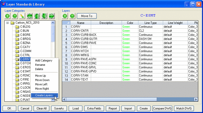
Create: After selecting
a Layer Category, you can pick this button to create all the layers
for that Category in the Drawing. When creating the layers, there
is an option to create a layer group filter for the CAD Layer
command.
 Compare DWG: This button is used to
Compare drawing layers and their associated properties such as
color, linetype, lineweight and plot style to the standard Library
definition for those layers. This feature will report how many
layers matched exactly, how many had a different set of properties
and how many non-Standard layers were found. It will also list the
non-standard layers which are those defined in the drawing but not
in the Library.
Compare DWG: This button is used to
Compare drawing layers and their associated properties such as
color, linetype, lineweight and plot style to the standard Library
definition for those layers. This feature will report how many
layers matched exactly, how many had a different set of properties
and how many non-Standard layers were found. It will also list the
non-standard layers which are those defined in the drawing but not
in the Library.
Match DWG: This button is used to alter the properties of drawing layers to match the properties of layers defined in the library, or vice versa. After picking the Match DWG button, this dialog box displays:

Pick the Library to DWG button to alter the
drawing layers to conform to the Library definitions.
Pick the DWG to Library button to alter the
Library definitions of the layers to conform to those set in the
drawing.