3D Viewer/Model Library
This command manages a collection of 3D graphic files and
defines how to render CAD entities in the 3D Viewer. The CAD to 3D
Viewer settings define how to translate different types of selected
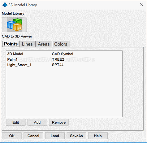
CAD entities into the 3D Viewer. The Points tab associates a
CAD block name with a 3D model. This way you can have a simple
symbol when working in CAD that is rendered as a complex 3D model
with viewing in the 3D Viewer. The Lines tab defines a 3D
model to use for linework on a specified layer. For example, a
polyline on a layer of FENCE in CAD can be assigned to render using
a fence 3D model. Besides defining the layer and 3D model, there is
also a setting for Gap which is the distance between the 3D models
along the linework. The Area tab defines textures to apply
to the surface model by closed CAD polylines on specified layers.
You can have different textures using nested closed polylines on
different layers and the texture for the inner polyline is used for
that inner area. For example, you can have an outer polyline on a
Parking layer for a texture of asphalt and inner polylines for
parking lot islands on an Island layer for a texture of grass. The
Colors tab applies to TIN surfaces that have colors assigned
to the 3D faces. This settings map TIN colors to textures for
rendering the TIN.
 The Model
Library button has the collection of 3D model files which can be
assigned to CAD symbols in the Points tab of CAD to 3D Viewer.
Also, these 3D Models can be added to the scene by using the Add
Model function in commands such as 3D Drive Simulation.
The Model
Library button has the collection of 3D model files which can be
assigned to CAD symbols in the Points tab of CAD to 3D Viewer.
Also, these 3D Models can be added to the scene by using the Add
Model function in commands such as 3D Drive Simulation.
The files are grouped by user-defined categories. The graphic
files can be either .dxf, .mdl or .obj format. SketchUp .skp files
can also be selected to add to the library. The program will
convert these .skp files into .obj format. The SaveAs and Load
functions allow you to save the model library to .mlib files for
sharing or backup. The current model library data is stored in the
Carlson USER folder in models.dta.
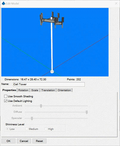
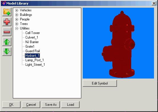 The Edit
Symbol function brings up another dialog with edit functions. In
the edit dialog, the program shows the dimensions of the model and
the number of data points.
The Edit
Symbol function brings up another dialog with edit functions. In
the edit dialog, the program shows the dimensions of the model and
the number of data points.
The Properties tab has controls for the lighting of the object
and whether to smooth the 3D faces of the object.
The Rotation function sets the default rotation for when the
object is inserted. The Random Rotate option makes the rotation
random for each time the object is inserted which applies to
objects like trees that are inserted multiple times and look better
with different rotations.
The Scale function sets the initial insertion scale. Often a
scale factor of 0.08333 is needed to convert a model in inches
units into feet for inserting into a scene in feet units. The X/Y/Z
axis can be scaled independently or uniformly. The scale can be set
directly by factors or by entering the model dimensions which is
handy for vehicle models when the dimensions of the vehicle are
known.
The Translation settings control the insertion point of the
model.
The Orientation setting for Force Vertical Orientation makes the
model level when inserted into the scene which applies to objects
like trees and buildings. Otherwise the models get inserted at the
slope of the surface at their position which is good for objects
like vehicles.
Pulldown Menu Location: Settings
Keyboard Commands: modellib
Prerequisite: None