Place Calls
This feature allows you to annotate C&G and CAD lines, arcs and
polylines.
Call Setup
Selecting Calls Setup will brings up the Call settings dialog
box.
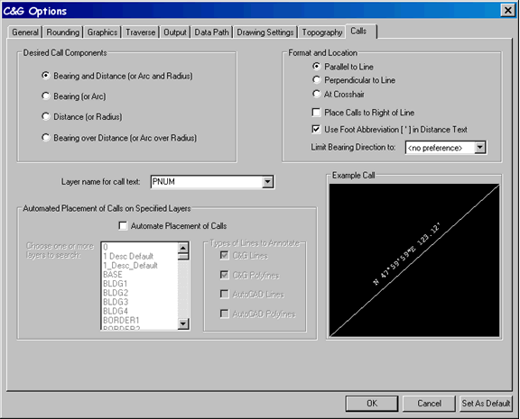
Desired Call Components:
Specify the desired components for the call.
Bearing and Distance (or Arc and Radius)
Bearing (Arc)
Distance (Radius)
Bearing over Distance (Or Arc over Radius)
If you specify points to form a curve then the components shown in
parentheses will be used to form the call text.
Format and location:
Specify how you want the call placed relative to the line or
arc:
Parallel: to the line or
Arc
Perpendicular: to the line
or arc
At Cursor: means the call
text will be drawn horizontally at the cursor and you must move it
to the desired location then left click to place it.
Place Call to Right of
Line: If you are placing a call either parallel or
perpendicular to a line or arc, select this box if you want the
call placed to the right of the line or arc, assuming you are
standing on the line and facing in the direction of the bearing.
The call will be centered along the line or arc.
Use the Foot Abbreviation [ ‘ ] in
Distance Text: Checking this box will places the [ ‘ ] mark
after the distance ( 125.36’ ). Un-checking the box will
remove the [ ‘ ] mark ( 125.36 ).
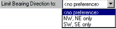
Line Bearing Direction
to:
Selecting NW,NE: will force
all calls to be shown only with NE and NW notation (N 428 35’ 12” E
or N 168 25’ 31” W)
Selecting SW,SE :will force
all calls to be shown only with NE and NW notation (S 428 35’ 12” E
or S 168 25’ 31” W)
If < no preference >:
is selected the software will define the bearing based on the
direction of the points selected.
Layer Name for Call Text:
Specify the layer where you want the calls placed.
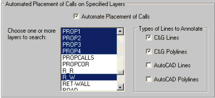
Automated Placement of Calls
on Specified Layers
Check the Automate Placement of Calls check box making the options
in the dialog active. This routine allows you to select one
or more layers to scan for the placement of calls. The scan
will look for lines only in the layers you specify even though
other layers may be currently displayed.
Choose one or more layers to search: this dialog will display the
complete list of layers in the drawing file. You can scroll
up and down the list and simple click with the mouse those layers
you want to search for lines/polylines.
Types of Lines to
Annotate:
C&G Lines and C&G
Polylines: refer to lines that have been drawn using the
CGDraw command, thus being based on the C&G coordinate
file.
CAD lines and CAD
Polylines: refer to lines that have been drawn using the CAD
Draw command and are not based on the C&G coordinate files.
Example Cell: this display
shows you the actual layout as it will appear on you drawing.
Prompts
When you choose the Place Calls menu item and a coordinate file is
not already open, you will be asked to open a coordinate
file. You will then see the following prompt at the command
line:
Enter point sequence:
[Point group/Reset/turn_sNap on/Setup/polYline] (last point =
<none>):
Point Group: If you press P
and <Enter> you will be asked to enter a point group and it
will be used to place calls automatically.
Reset: Press "R" resets the
last point ID to <none>
sNap on or sNap off: Press
"N" turns the CAD snaps on
or off. When the command starts the AutoCAD snaps are off by
default.
The Setup: Press "S" option
brings up the Calls Setup dialog box.
polYline: if you Press"Y"
and <Enter> you can then pick a C&G polyline and it will
be annotated in the order that the vertices were specified when it
was drawn.
Pulldown Menu Location:
CG-Survey > CGDraw>Calls>Place Calls
Keyboard Command: CALL,
CG_CALLS or CALS, CG_CALLS_SETUP
Prerequiste:
Coordinate file