
Underground
Project Manager
The Underground Project Manager (MPD) file should be defined before
stating with Underground Mine Layout and Timing using the
Underground Project Manager command under Underground menu. It
allows user to define Equipments, Timing Calendar, Panel Attributes
as well as other essential parameters to be used in the
timing.
Mine Layout
Options
Using the Advanced Projections command in the Basic Mining Module,
there are several ways the user can generate mine projections.
These different techniques will be based upon personal preference
and management’s direction. Whether or not to include the
centerlines, pillars, and perimeters on the map are up to the user.
The Advanced Mine Module timing routines require that some
information is kept on specific layers. The pillars must be drawn
on the PILLARS layer and the perimeter of each section must be
drawn on the PERIM layer. These are the defaults set in the
Advanced Projections option under the Basic Mine Module.
After responding to the initial prompts the Panel Settings dialog box appears. This dialog box allows the user to specify how the mine projections will be drawn. Several different variations are possible. Entry spacing and length can be varied, separately or together.

A nice feature of Carlson is that it allows the user to draw the rooms on one or both sides of the panel at the same time the panel is drawn. The rooms perimeter on the left or right side can also be joined to the panel perimeter so the timing blocks will match for the panel and the rooms.

In addition to the configuration of the pillars, the user has the option of what to display, pillars, centerlines, perimeter, as well as chamfer, angled blocks, bracketed pillars, stoppings, and ventilation.

As you can see there are several options to present mine projections with Carlson.
Once the panels have been laid out, they have to be “placed”, or have extended entity data attached to them, so that they will relate to each other. Carlson has three different methods of placing panels: Place Panel, Pick & Place, and Auto Place by Text. Of these three techniques only Place Panel builds a network topology, or precedence relationship, between the panels as they are placed. With the other two techniques, Pick & Place and Auto Place by Text, there is no relationship built as they place the panels. This allows the user to actually mine through panels that overlay each other, which could be helpful in laying out mining though overlying strata.
Place
Panel
To place panels, the panels must be previously drawn with the
perimeter drawn in the PERIM layer and the pillars, which are
optional, drawn in the PILLARS layer. The program subtracts the sum
of the areas of the individual pillars in the PILLARS layer from
the area of the perimeter drawn in the PERIM layer to calculate the
extraction ratio. The extraction ratio is then applied to the
perimeter area to calculate the tonnage in the panel.
In the Advanced Mine Module under the Underground dropdown box you will find Place Panel. When the user selects Place Panel the first prompt is:
Use Quick Place mode (yes/<no>)? Quick place mode is an option that lets the user place panels without entering specific information in the panels other then the panel name. It is a way to get the panels placed quickly. If the user has drawn the pillars and does not intend to retreat mine, the Quick Place mode may be the best way to get the panels placed.
If the user chooses the Quick Place mode the following prompts appear:
Start new mine plan? (yes/<no>)? The user will always respond with yes for the first panel. Next, as long as the panels being placed are adjacent, the response is negative. Panels that are part of the same mine plan, but are physically separated can be placed as new mine plans and connected later.
The next prompt is: Direction of panel is defined by (<Perim>,Text, PIck, Segment)?
When the direction of mining has been set. The program prompts
for the name of the panel, offering a name that can be accepted or
overwritten. When the name is entered, the program draws the green
“backbone” line according to the direction of mining and places the
name of the panel at the beginning of the line. The user clicks the
right button to complete this process for mining straight through a
panel.
To mine around a corner the user left picks the mouse button and repeats the above steps for setting the direction.

Once the panel has been placed, the program prompts the user for the entry to branch from. The program is asking for the point along the “backbone” line to start the next panel. Once the user selects the starting point for the next panel the process repeats.
Using the Quick Place mode does not give the user access to the Edit Section Data dialog box during the panel placing process. If the pillars are not drawn when using the Quick Place mode the user will have to return to the Edit Section Data dialog box to enter the extraction ratio after placing the panels. Most users prefer to enter this information when the panel is being placed, so they usually do not use the Quick Place mode.
If the user chooses not to use the Quick Place mode there are two additional panel direction options available: Azimuth and Pick internal point.


Pick and
Place
Pick and Place places and times the panel as it is placed, drawing
the timing blocks when the panel is placed. In addition to timing
as it goes, this option allows the user to test the schedule before
placing the panel in the mining sequence, providing real time
feedback while scheduling the mine. This technique does not
automatically build precedence between panels automatically.
Precedence can be added to the panels in the precedence part of the
Edit Section Data dialog box. Once all of the individual panels
have been placed, the user runs the schedule to get the complete
mine timing report.

Auto Place Panel
by Text
The Auto Place Panel by Text command gives the user the ability to
place panels by drawing text in the panel perimeters on the PANELNM
layer. The requirement for drawing the perimeter in the PERIM layer
is the same. The prompts are set out below.
Command: auto_place
Assign zero retreat extraction (Yes/<No>)?
Advance difficulty <1.0> :
Retreat difficulty <1.0> :
Retreat recovery ratio for remaining pillars <1.0> :
Entry width <20.0> :

Panel
Attributes
The default panel attributes option lets the user assign attributes
by value or grid. Certain key or reserved words are available to
the user that Carlson recognizes. Choose the Keywords Help button
to see them:


Define
Equipment
Define Equipment is where the user adds and edits the production
rate of the equipment, it can be accessed from Underground Project
Manager. Production rates are input for the entire spread or
section. This rate can be modified as a function of time, mining
height, or strip bench. The Rate/Shift, Hours/Shift, and Rate/Hour
back-calculate, allowing the user the ability to fine tune the
production rate. If the toggle to "Define Crews and Units" is on it
gives user an ability to define Labor Crews and Units (combination
of Crew and Equipment) separately.


The user can specify the minimum and maximum mining heights.
Where mining occurs below the minimum mining height out of seam
dilution is added to make up the desired minimum height. When the
maximum mining height is selected key strata is combined with
non-key material where the key strata exceeds the maximum mining
height. A cost per hour can be input and it will be multiplied by
the hours worked. Maintenance frequency is scheduled in the same
units as the Rate/Shift. The delays apply to the entire spread or
section in shifts for both Routine and Main Maintenance
Frequencies. The recovery factor is designed to be used with
elliptical cross-sectioned entries developed with boring
machines.
Calendar
The Editing Calendar is a quick and simple way to schedule a
production Equipment or Unit (group of a Equipment and Labor Crew
working on it). This should be thought of as an equipment, as
opposed to a crew scheduling technique. Equipment needs to be added
before the calendar is applied. The calendar can be applied to a
single unit or all of the equipment. To apply the calendar to
several units select the calendar and the unit and Apply the
calendar to the unit. Once the calendar is created two different
reports can be generated. The first report is the annual unit
calendar and the second is a yearly report of what is working and
when.

Pin
Points
Pin points are break points set in a panel to indicate where the
mining temporarily stops to facilitate mining in other areas. When
mining resumes in the panel with the pin point it resumes at the
pin point. Pin points allow the user to layout fewer panels.

Underground
Timing
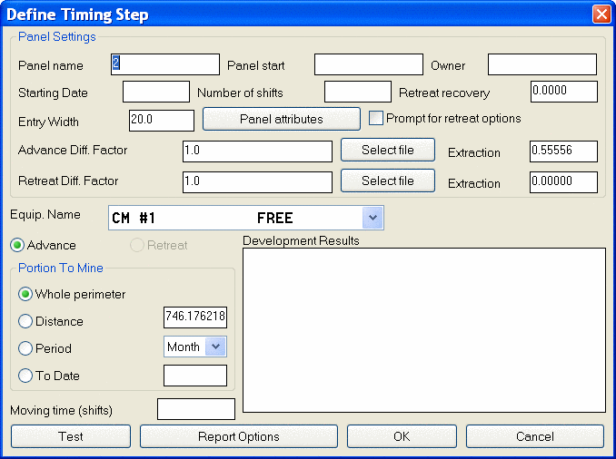
The Underground Timing option is selected after the panels have
been placed, and the equipment and calendar have been defined.
Panels are assigned to equipment in the sequence to be mined.
Panels can be selected by name from the unassigned list or screen
picked. The unassigned panel list can be sorted by name or
direction of mining. Delays can be scheduled between panels in days
or shifts. The starting date and number of shifts per day are
assigned in the designated boxes. Once the run is set up, left
click on the Calculate button. Two reporting options are then
available. An abbreviated timing report can be viewed or the
detailed timing report can be formatted. The user has a wide range
of timing options that impact the presentation of the timing
map.


Once the report options are selected the map is timed out.

When the report times the map it also develops a report. The report formatter allows the user to customize the report. By moving available variables across to the used variables side in the order from top to bottom the user can set the order in the report. This order also drives the sub-totaling option to create various report styles. The report can be displayed on the screen, printed, made part of the drawing, or exported to Excel or Access. The order set up in the report format from top to bottom is the order in the report from left to right. There is a line editor in the screen display that allows the user to add lines and edit the report prior to printing.

This is an example of exporting the report to a spreadsheet. Totals can be exported to spreadsheets as an option. If totals are exported they show up in bold font. This report can also be imported into the Microsoft Access database for additional reporting options.

Underground
Project Manager
The Underground Project Manager (MPD) file should be defined before
starting with Underground Mine Layout and Timing using the
Underground Project Manager command under Underground menu. It
allows user to define Equipments, Timing Calendar, Panel Attributes
as well as other essential parameters to be used in the
timing.
Mine Layout
Options
Using the Advanced Projections command in the Basic Mining Module,
there are several ways the user can generate mine projections.
These different techniques will be based upon personal preference
and management’s direction. Whether or not to include the
centerlines, pillars, and perimeters on the map are up to the user.
The Advanced Mine Module timing routines require that some
information is kept on specific layers. The pillars must be drawn
on the PILLARS layer and the perimeter of each section must be
drawn on the PERIM layer. These are the defaults set in the
Advanced Projections option under the Basic Mine Module.
After responding to the initial prompts the Panel Settings dialog box appears. This dialog box allows the user to specify how the mine projections will be drawn. Several different variations are possible. Entry spacing and length can be varied, separately or together.
A nice feature of Carlson is that it allows the user to draw the rooms on one or both sides of the panel at the same time the panel is drawn. The rooms perimeter on the left or right side can also be joined to the panel perimeter so the timing blocks will match for the panel and the rooms.
In addition to the configuration of the pillars, the user has the option of what to display, pillars, centerlines, perimeter, as well as chamfer, angled blocks, bracketed pillars, stoppings, and ventilation.
As you can see there are several options to present mine projections with Carlson.
Once the panels have been laid out, they have to be “placed”, or have extended entity data attached to them, so that they will relate to each other. Carlson has three different methods of placing panels: Place Panel, Pick & Place, and Auto Place by Text. Of these three techniques only Place Panel builds a network topology, or precedence relationship, between the panels as they are placed. With the other two techniques, Pick & Place and Auto Place by Text, there is no relationship built as they place the panels. This allows the user to actually mine through panels that overlay each other, which could be helpful in laying out mining though overlying strata.
Place
Panel
To place panels, the panels must be previously drawn with the
perimeter drawn in the PERIM layer and the pillars, which are
optional, drawn in the PILLARS layer. The program subtracts the sum
of the areas of the individual pillars in the PILLARS layer from
the area of the perimeter drawn in the PERIM layer to calculate the
extraction ratio. The extraction ratio is then applied to the
perimeter area to calculate the tonnage in the panel.
In the Advanced Mine Module under the Underground dropdown box you will find Place Panel. When the user selects Place Panel the first prompt is:
Use Quick Place mode (yes/<no>)? Quick place mode is an option that lets the user place panels without entering specific information in the panels other then the panel name. It is a way to get the panels placed quickly. If the user has drawn the pillars and does not intend to retreat mine, the Quick Place mode may be the best way to get the panels placed.
If the user chooses the Quick Place mode the following prompts appear:
Start new mine plan? (yes/<no>)? The user will always respond with yes for the first panel. Next, as long as the panels being placed are adjacent, the response is negative. Panels that are part of the same mine plan, but are physically separated can be placed as new mine plans and connected later.
The next prompt is: Direction of panel is defined by (<Perim>,Text, PIck, Segment)?
When the direction of mining has been set. The program prompts
for the name of the panel, offering a name that can be accepted or
overwritten. When the name is entered, the program draws the green
“backbone” line according to the direction of mining and places the
name of the panel at the beginning of the line. The user clicks the
right button to complete this process for mining straight through a
panel.
To mine around a corner the user left picks the mouse button and repeats the above steps for setting the direction.
Once the panel has been placed, the program prompts the user for the entry to branch from. The program is asking for the point along the “backbone” line to start the next panel. Once the user selects the starting point for the next panel the process repeats.
Using the Quick Place mode does not give the user access to the Edit Section Data dialog box during the panel placing process. If the pillars are not drawn when using the Quick Place mode the user will have to return to the Edit Section Data dialog box to enter the extraction ratio after placing the panels. Most users prefer to enter this information when the panel is being placed, so they usually do not use the Quick Place mode.
If the user chooses not to use the Quick Place mode there are two additional panel direction options available: Azimuth and Pick internal point.
Pick and
Place
Pick and Place places and times the panel as it is placed, drawing
the timing blocks when the panel is placed. In addition to timing
as it goes, this option allows the user to test the schedule before
placing the panel in the mining sequence, providing real time
feedback while scheduling the mine. This technique does not
automatically build precedence between panels automatically.
Precedence can be added to the panels in the precedence part of the
Edit Section Data dialog box. Once all of the individual panels
have been placed, the user runs the schedule to get the complete
mine timing report.
Auto Place Panel
by Text
The Auto Place Panel by Text command gives the user the ability to
place panels by drawing text in the panel perimeters on the PANELNM
layer. The requirement for drawing the perimeter in the PERIM layer
is the same. The prompts are set out below.
Command: auto_place
Assign zero retreat extraction (Yes/<No>)?
Advance difficulty <1.0> :
Retreat difficulty <1.0> :
Retreat recovery ratio for remaining pillars <1.0> :
Entry width <20.0> :
Panel
Attributes
The default panel attributes option lets the user assign attributes
by value or grid. Certain key or reserved words are available to
the user that Carlson recognizes. Choose the Keywords Help button
to see them:
Define
Equipment
Define Equipment is where the user adds and edits the production
rate of the equipment, it can be accessed from Underground Project
Manager. Production rates are input for the entire spread or
section. This rate can be modified as a function of time, mining
height, or strip bench. The Rate/Shift, Hours/Shift, and Rate/Hour
back-calculate, allowing the user the ability to fine tune the
production rate. If the toggle to "Define Crews and Units" is on it
gives user an ability to define Labor Crews and Units (combination
of Crew and Equipment) separately.
The user can specify the minimum and maximum mining heights.
Where mining occurs below the minimum mining height out of seam
dilution is added to make up the desired minimum height. When the
maximum mining height is selected key strata is combined with
non-key material where the key strata exceeds the maximum mining
height. A cost per hour can be input and it will be multiplied by
the hours worked. Maintenance frequency is scheduled in the same
units as the Rate/Shift. The delays apply to the entire spread or
section in shifts for both Routine and Main Maintenance
Frequencies. The recovery factor is designed to be used with
elliptical cross-sectioned entries developed with boring
machines.
Calendar
The Editing Calendar is a quick and simple way to schedule a
production Equipment or Unit (group of a Equipment and Labor Crew
working on it). This should be thought of as an equipment, as
opposed to a crew scheduling technique. Equipment needs to be added
before the calendar is applied. The calendar can be applied to a
single unit or all of the equipment. To apply the calendar to
several units select the calendar and the unit and Apply the
calendar to the unit. Once the calendar is created two different
reports can be generated. The first report is the annual unit
calendar and the second is a yearly report of what is working and
when.
Pin
Points
Pin points are break points set in a panel to indicate where the
mining temporarily stops to facilitate mining in other areas. When
mining resumes in the panel with the pin point it resumes at the
pin point. Pin points allow the user to layout fewer panels.
Underground
Timing
The Underground Timing option is selected after the panels have
been placed, and the equipment and calendar have been defined.
Panels are assigned to equipment in the sequence to be mined.
Panels can be selected by name from the unassigned list or screen
picked. The unassigned panel list can be sorted by name or
direction of mining. Delays can be scheduled between panels in days
or shifts. The starting date and number of shifts per day are
assigned in the designated boxes. Once the run is set up, left
click on the Calculate button. Two reporting options are then
available. An abbreviated timing report can be viewed or the
detailed timing report can be formatted. The user has a wide range
of timing options that impact the presentation of the timing
map.
Once the report options are selected the map is timed out.
When the report times the map it also develops a report. The report formatter allows the user to customize the report. By moving available variables across to the used variables side in the order from top to bottom the user can set the order in the report. This order also drives the sub-totaling option to create various report styles. The report can be displayed on the screen, printed, made part of the drawing, or exported to Excel or Access. The order set up in the report format from top to bottom is the order in the report from left to right. There is a line editor in the screen display that allows the user to add lines and edit the report prior to printing.
This is an example of exporting the report to a spreadsheet. Totals can be exported to spreadsheets as an option. If totals are exported they show up in bold font. This report can also be imported into the Microsoft Access database for additional reporting options.