Road Rehabilitation
This lesson designs a road rehabilitation project for two lanes
of an Interstate highway. The top surface of the existing road has
already been milled and the top of the milled surface has been
surveyed. The two lanes are crowned in the center with a typical
cross slope of approximately 1%. The design is to add 8" of
concrete with a minimum cross slope of 1.56%.
Getting Started
To begin, let's open the project drawing and verify the proper
menu configuration is loaded.
- Open the drawing named rehab1_tutorial.dwg
installed in the Carlson Projects folder by default.
- Make sure the Civil menu configuration is loaded. From the
Settings menu, click Carlson Menus → Civil Menu.
Create Existing Surface
Our goal in this section is to create an existing ground surface
model named Exist-rd.tin. For input, there are survey
points for the existing base and polylines for the centerline and
edges of pavement.
- From the Surface menu, click Triangulate & Contour and set
the values shown in the dialog box below. Of particular note are
the following settings:
- Write Triangulation File is enabled with the file name
specified.
- Use Inclusion/Exclusion Areas is disabled.
- Shrink-Wrap Perimeter Reduction is set to
Medium.
- Ignore Zero Elevations is enabled.

- Click the OK button on the dialog box and follow the prompts
below:
Select the points and breaklines to
Triangulate.
Select objects: Type ALL and press Enter.
Select objects: press Enter
Writing Triangulation File: C:\Carlson
Projects\Exist-rd.tin
This concludes the creation of an existing surface model of the
milled roadway surface.
Create Centerline
Our next task will be to create a horizontal centerline from
polyline data found in the drawing. Before we complete this task,
we'll want to freeze the BREAKLINE layer to expose the
polylines on the PROPOSED PAVEMENT layer.
- From the View menu, click Freeze Layer and follow the
prompts:
Pick entities on layers to be
frozen.
Select entities: Pick one of the pavement edge polylines and press Enter
when complete.
Freezing layer: BREAKLINE
- From the Centerline menu, click Polyline To Centerline File to
create a CL file from the center polyline in the drawing.
- Enter a file name of rehab.cl, pick the
polyline and enter a beginning station of 73258.51.
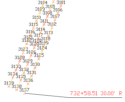
Create Existing Sections
Now that the horizontal path of the road has been established,
the next step will be to generate cross-section information of
existing conditions.
- From the Sections pull-down menu, choose Input-Edit Section
Alignment and supply a section alignment name of
rehab.mxs.
- At the centerline prompt, type C (for
"CL File") and select the rehab.cl file created
earlier.
- For the Alignment Settings, set the Station Interval to 25 and
the Left/Right Offset values to 50.

- Click the OK button and then click the Save button on the next
dialog box showing the list of the section stations.
- Create the actual cross-section data through the Sections →
Create Sections From → Sections from Grid or Triangulation Surface
command and select:
- exist-rd.tin as the source of the surface model
- "Prompt" as the linking method between the surface
model and the output section file.
Note: With the prompt option, should the
definition of the surface model change, you will be prompted if
section data should update as well!
- rehab.mxs as the section alignment
- exist-rd.sct as the output section file
This completes the generation of the cross-sectional data of the
existing, milled road.
Design Template
Now that we've generated existing cross-section data, our next
task will be to create a design template "overlay" for the road
surface we wish to construct:
- From the Roads menu, click Design Template and create a new
template file named rehab.tpl.
- Click the Grades button and indicate the following
desired values for the pavement grade surface:
- -2% Linear Slope
- 12 feet for the Horizontal Distance
- EP for an ID of "edge of pavement"
Click OK to dismiss the Grade Dimensions dialog box.
- Click the Subgrade button and indicate the following
desired values for the subgrade surface:
- Straight Up for the Intersect Surface option. This
instructs the subgrade surface to intersect vertically to the grade
surface above.
- 0 for the horizontal offset distance. This instructs
the subgrade surface to start directly under the centerline of the
road.
- -8 inches for the Vertical Offset. This instructs the
subgrade to be 8 inches below the grade surface above and will
generate the minimum 8" pavement thickness specified earlier in
this lesson.
- EP for the Distance. This instructs the subgrade width
to be the same width as the EP (edge-of-pavement) width specified
in the Grade Dimensions.
Note: By using the parametric/variable ID points
(e.g. the "EP" code vs the 12' Horizontal
Distance, the subgrade width will vary as needed to accommodate the
pavement grade width!
- Concrete for the Material.
- Click OK when ready to dismiss the Grade Dimensions dialog box.
The proposed road template should resemble the following:
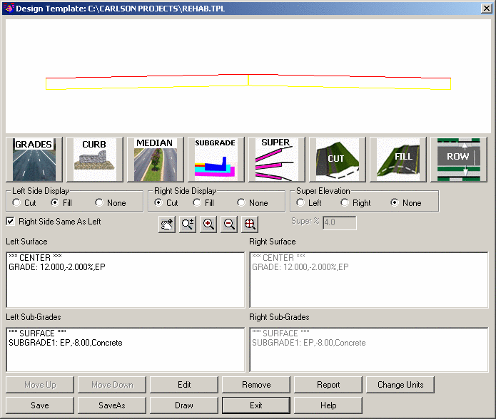
- That's all that needs to be defined in the template. Click the
Save button and then click Exit.
This completes the proposed definition of the new pavement
overlay.
Template Grade Table
The next step is to design the proposed cross-slopes to follow
the existing section grades as much as possible.
- From the Roads menu, click Template Grade Table and create a
new Template Grade Table file named rehab.tgt and
specify the rehab.tpl created earlier as the template file
to process.
- Highlight the GRADE surface from the Left Surface list
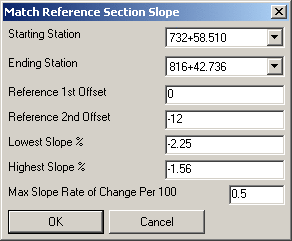
and click the Match Slope button and identify the
exist-rd.sct file as the Section File to Process.
- For the Match Slope options, specify:
- 0 for Reference 1st Offset
- -12 for Reference 2nd Offset
Note: These values sample the existing sections at
the offsets specified to get the existing cross slope.
- -2.25 for the Lowest Slope %
- -1.56 for the Highest Slope %
Note: These values restrict the design
cross-slopes to be within the range specified.
- 0.5 for the Max Slope Rate of Change Per 100. This
restricts how much the design cross-slope can change between
stations. For example, with the maximum set to 0.5 and a
cross-slope of -2.0% at station 1+00, the cross-slope at station
2+00 must be between -2.5% and -1.5%.
- After picking OK on this dialog, highlight the right side grade
and pick the Match Slope button.
- Use the same parameters as the left side except use Reference
Offsets of 0 and 12 and then pick OK.
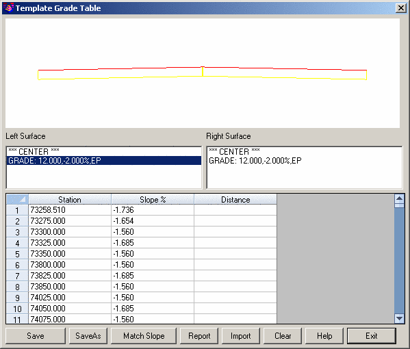
- From the Template Grade Table dialog box, click Save and then
click Exit.
This completes the process of generating a Template Grade
Table.
Design Profile
The next step is to define the design profile that minimizes
quantities while satisfying the design parameters.
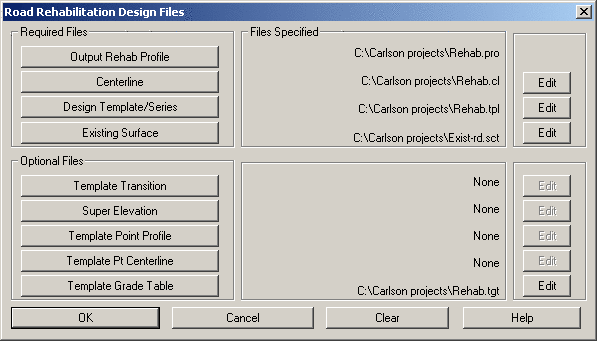
- From the Roads menu, click the Road Rehabilitation Profile
command and specify a new file name
rehab.pro.
- For the Centerline, Design Template, Existing Surface and
Template Grade Table, choose the files created in the previous
steps as shown below:
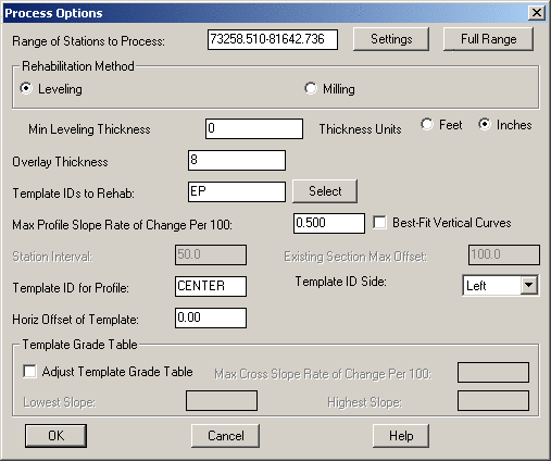
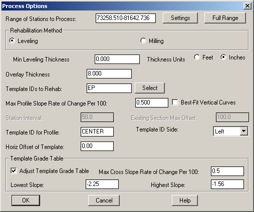
- Click the OK on the file selection dialog to get to the Process
Options dialog and specify the following values:
- Leveling for the Rehabilitation Method
- 0 inches for the Minimum Leveling Thickness
- 8 inches for the Overlay Thickness (the same as the
Subgrade thickness defined in the Design Template).
- EP for the Template IDs to Rehab (the same as the
pavement edge ID defined in the Design Template).
- 0.5 for Max Profile Slope Rate of Change Per 100 to
restrict the rate of profile grade change.
Note: This setting is similar to the Max Slope
Rate of Change Per 100 in Match Slope for Template Grade Table
except this one applies to the profile slope instead of the
cross-slope.
- Leave the rest of the settings as the defaults as shown.
- Click the OK button to process and generate the desired
rehab.pro file.
This completes the process of generating a design profile.
Adjustments to the profile can be made through the Profiles →
Design Road Profile → Input-Edit Road Profile command.
Process Road Design
The road design is now ready to be computed.
- From the Roads menu, initiate the Process Road Design
command.
- Make sure the Centerline, Profile, Design Template, Existing
Surface and Template Grade Table options are each utilizing the
files created earlier.
- Click on the Design Section button to create a
new file named Final-rd.sct as illustrated below:
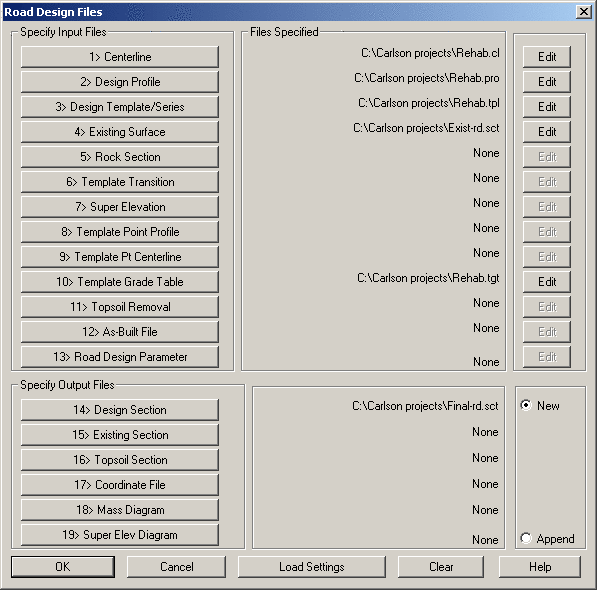
- Click OK when ready to continue.
- On the Additional Road Design Parameters dialog box, accept the
default values and click OK to initiate the processing of the
design.
The program reports the quantities per station and totals in a
report similar to that shown below:
Process Road Design

Template File> C:\Carlson Projects\rehab.tpl
Profile File> C:\Carlson Projects\rehab.pro
Existing Surface File> C:\Carlson Projects\exist-rd.sct
Centerline File> C:\Carlson Projects\rehab.cl
Template Grade Table File> C:\Carlson Projects\rehab.tgt
Design Section Output File> C:\Carlson Projects\Final-rd.sct

Processing 732+58.510 to 816+42.736
Total Cut : 0.001 C.F., 0.000 C.Y.
Total Fill: 12449.816 C.F., 461.104 C.Y.
Cut to Fill Ratio: 0.00
Total Left Subgrade1 - Concrete: 33533.838 C.F., 1241.994 C.Y., 100603.375 S.F., 11178.153 S.Y.
Total Right Subgrade1 - Concrete: 33533.140 C.F., 1241.968 C.Y., 100601.280 S.F., 11177.920 S.Y.
Note: Be aware of the following important
values:
- The Total Fill is the amount of extra leveling.
- The Subgrade Volumes are the amount of overlay.
This completes an initial process of the design data.
Draw Sections
Our next task will be to visually verify the design by
generating cross-section plots.
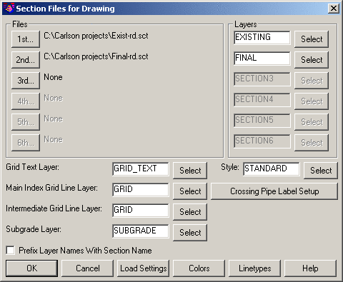
- From the Sections menu, click Draw Section File. Set the 1st
section file to Exist-rd.sct and the 2nd section file to
be Final-rd.sct as illustrated below:
- On the Draw Section File dialog box, set the following
values:
- 10 for the Horizontal Scale value.
- 5 for the Vertical Scale value.
- Click the Scan Files to Set Defaults button to "read"
the section files specified earlier and retrieve data from
them.
- Vertical Stack for the Type of Plot.
- Enable the Label Slopes option and then click the
Set button to ensure:
- Label Section 1 is enabled.
- Label Section 2 is enabled.
- Click the OK button and then screen pick a point in a blank
area of the drawing.
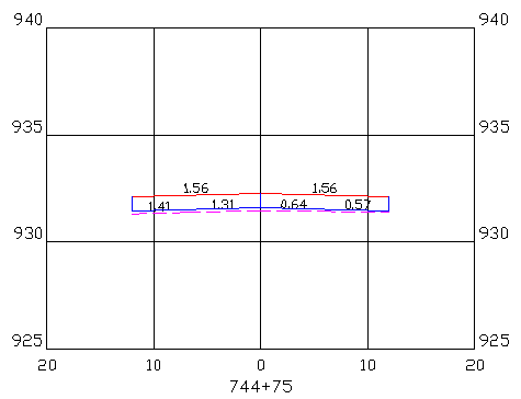
This station shows the existing surface with slopes ranging from
1.41% left to 0.57% right and the design with slopes 1.56% left and
right. Since 1.56% was the minimum design cross slope, the design
is steeper than existing and there is some leveling needed between
the design overlay and the existing.
The profile elevation for this station was set by the right edge
since this was the highest point. There is some extra leveling fill
needed on the left side. This left side slope can be steeper
because our design cross-slope range is 1.56% to 2.25%.
Let's continue with additional steps to refine the design!
Design Profile (with Template Grade Adjustment)
From the Roads menu, re-run the Road Rehabilitation Profile
command again.
- Use all the same files for the first dialog.
- On the second dialog, enable the Adjust Template Grade Table
toggle and set the Lowest and Highest Slopes and the Max Cross
Slope Rate to the same design parameters used during Template Grade
Table as shown below:
- Click the OK button when ready.
Note: The Adjust Template Grade Table
option checks the left and right grades while creating the
rehabilitation profile and adjusts the slope on the side that is
not controlling the profile grade.
Process Road Design (with Template Grade Adjustment)
From the Roads menu, issue the Process Road Design command again
with all the same settings from the previous run.
Process Road Design

Template File> C:\Carlson Projects\rehab.tpl
Profile File> C:\Carlson Projects\rehab.pro
Existing Surface File> C:\Carlson Projects\exist-rd.sct
Centerline File> C:\Carlson Projects\rehab.cl
Template Grade Table File> C:\Carlson Projects\rehab.tgt
Design Section Output File> C:\Carlson Projects\Final-rd.sct

Processing 732+58.510 to 816+42.736
Total Cut : 21.607 C.F., 0.800 C.Y.
Total Fill: 11152.921 C.F., 413.071 C.Y.
Cut to Fill Ratio: 0.00
Total Left Subgrade1 - Concrete: 33533.761 C.F., 1241.991 C.Y., 100603.375 S.F., 11178.153 S.Y.
Total Right Subgrade1 - Concrete: 33533.107 C.F., 1241.967 C.Y., 100601.280 S.F., 11177.920 S.Y.
For this run, the Template Grade Table has been adjusted. In the
report, the overlay quantities are the same and the fill quantity
for the extra leveling has been reduced as expected. In this case,
the Template Grade Adjustment reduced the Total Fill (extra
leveling) amount from 461.104 C.Y. to 413.071 C.Y. (about a 10%
reduction in needed leveling material).
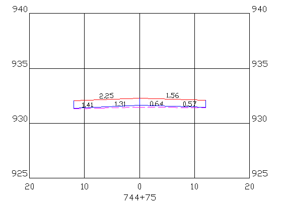
Draw Sections
From the Sections menu, click Draw Section File command to
redraw the sections data again using all the same settings. The
only difference in the final section is that the left side is
steeper to better match the existing surface.
This concludes this tutorial lesson on roadway
rehabilitation.