
4 Under the Survey menu, select Enter Deed Description. The following dialog box will appear so you can specify where to store the coordinates:
In this short lesson you will create a simple drawing. You will enter a 6-sided deed, add a title block, bar scale, and north arrow, add a title and certification text, and plot the deed area.
Note that the Esc key will cancel most commands, so if you choose the wrong command or enter something incorrectly and want to start over, just press Esc.
1 Click the icon for Carlson. You may be presented with a Startup Wizard dialog box. If so, click Exit.
2 Under the Settings menu, click Drawing Setup. Set the unit setting to English and the Horizontal Scale to 50. Click OK.

4 Under the
Survey menu, select Enter Deed Description. The following
dialog box will appear so you can specify where to store the
coordinates:
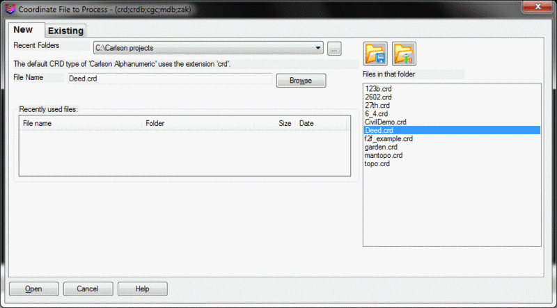
Now use the default settings as shown in this
dialog box image. Click OK.

When you are prompted for a description, enter "Fence Post".
Exit/Curve/<Bearing
(Qdd.mmss)>: 125.3500
The quadrant (Q) is 1 for Northeast (2 is Southeast, 3 is Southwest
and 4 is Northwest). The bearing is 25 degrees, 35 minutes, and 00
seconds. If all digits for the minutes and seconds are entered as
shown above, then the deed call will be fully plotted, including
the seconds. If only the degrees and minutes were entered, as in
125.35, then the plot would appear as "N 25d 35' E".
Varas/Meters/Poles/Chains/<Distance(ft)>:
200.51
Note that you can enter old deeds in the forms of Poles and Links,
Chains and Links and even Varas (a unit of measurement formerly
used in the southwestern states of the U.S.).
Enter Point Description <Fence
Post>: Iron Pin
Undo/Exit/Curve/<Bearing
(Qdd.mmss)>: 189.4321
Varas/Meters/Poles/Chains/<Distance(ft)>:
225.00
Enter Point Description <Iron
Pin>: press Enter
Pressing Enter selects the default, which is Iron Pin.
Undo/Exit/Curve/<Bearing
(Qdd.mmss)>: C
Tangent-out/<Radius>: 75
Curve direction
[Left(-)/<Right(+)>]? press
Enter for right
Non-tangent/Reverse-tangent/Bearing/Chord/DeltaAng/Tangent/<Arc
Len>: 118.17
If you don't know the arc length, but you know the tangent, you
would choose "T" for tangent.
Enter Point Description <Iron
Pin>: press Enter
Undo/Exit/Curve/<Bearing
(Qdd.mmss)>: 200.0000 (due
South)
If you were to enter just 2 (no degrees, minutes, or seconds), then
the deed call would be plotted "S 000 E".
Varas/Meters/Poles/Chains/<Distance(ft)>:
178.00
Enter Point Description <Iron
Pin>: Concrete
Monument
Undo/Exit/Curve/<Bearing
(Qdd.mmss)>: 488.2300
This entry specifies Northwest 88 degrees, 23 minutes.
Varas/Meters/Poles/Chains/<Distance(ft)>:
300.34
Enter Point Description <Concrete
Monument>: Fence Post
Undo/Exit/Curve/<Bearing
(Qdd.mmss)>: 454.1109
Varas/Meters/Poles/Chains/<Distance(ft)>:
106.93
Enter Point Description <Fence
Post>: press Spacebar, then press
Enter
Simply pressing Enter uses the default text (Fence Post) again. To
avoid drawing the text "Fence Post" twice on the end point, press
the spacebar, skip a blank character, and press Enter.
You have now completed the 6-sided figure (including one
curve).
Undo/Exit/Curve/<Bearing
(Qdd.mmss)>: E
The following results are reported:
Closure error distance> 0.01709  Error Bearing> S 52d5'26" E

Closure Precision> 1 in 66076.892  Total Distance Traversed> 1128.950
The resulting deed, has a closure of 1:66077. In the initial prompt "Undo/Exit/Curve...", U for Undo would allow you to reenter the previous deed call.
Use the Extents command on the View menu to see the entire area. Then choose Zoom Out under the View menu giving you adequate room for the next step.
5 Under the Settings menu, select Title Block. The dialog you will see is shown here:


Use the Extents command, found in the View menu, to see the entire working area. If you want to move the border, use the Move command on the Edit menu. Pick the border lines and the title block objects (up to 3 picks total), press Enter (to end object selection), then pick two points representing the vector of the move.
If you want to see a margin around the working area after you use the Extents command, use the Zoom Out command on the View menu. Then use the Window command on the View menu to capture the view and margin you prefer.
If you make a mistake, enter U for undo, or select the back arrow icon that appears at the top of the screen.
6 On the Annotate menu, select Draw North Arrow.
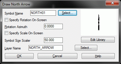
Accept the default north arrow that is shown at the right side of the dialog, click OK, and place it in the upper right of your drawing. Choose Move on the Edit menu (or Enter M for move at the command line) and move it.
7 On the Annotate menu, select Draw Barscale. Accept the defaults, and then pick an insertion point below the north arrow and directly above the "a" in Farmer, and approximately the same distance from both. You can move the bar scale using the Move command on the Edit menu, if you need to do so.
8 On the Draw menu, select Standard within the Text command. Respond to the prompts as shown below:
Specify start point of text or
[Justify/Style]: J for
justify
Enter an option
[Align/Fit/Center/Middle/Right/TL/TC/TR/ML/MC/MR/BL/BC/BR]: C
for center justified
Specify center point of text:
pick a point near the top-center of the
drawing
Specify height <4.00>:
10 Entering 10 makes the title text
bigger than the default.
Specify rotation angle of text
<E>: E
Text: Farmer
Survey
Text: Ashland,
KY
Text: press Enter
To enter a certification in the lower-right of the drawing, again select Text > Standard from the Draw menu, or type "dtext" at the command line. If you haven't done anything else, such as Zoom or Pan, you can simply press Enter to repeat the last command. If pressing Enter does not repeat the Text command, press Esc to cancel. Enter Dtext at the command prompt, and respond to the resulting prompts as shown below.
Pick a point above and to the left of the title block for the certification. You don't have to enter L for left-justification. The Dtext command defaults to left-justification every time.
Height <10.00>: 4
Rotation angle <E>: press Enter
Text: Surveyor's
Certification
Text: press spacebar, then press Enter
Text: I do hereby
certify that the survey shown hereon
Text: is a true
and correct representation...
Text: press
spacebar, then press Enter
Text: _____________________________________
Text: Arnold
James, PLS #2534
Text: press Enter
twice to end
The following is a closeup of the certification, north arrow,
and bar scale that we just entered:

9 Enlarge the two title lines ("Farmer Survey" and "Surveyor's Certification") by a factor of 2.0 using the command Text Enlarge/Reduce on the Edit menu, option Text. When prompted for Scaling Multiplier, enter 2. Select both the Farmer Survey text (at the top of the screen, not in the title block) and the Surveyor's Certification text. When asked again to Select Objects, press Enter.
When you are selecting objects, if you select something you don't want, you can enter "R" at the next Select Objects prompt, and remove items from the selection set. If you want to add objects after you have removed an object, enter "A" at the next Select Objects prompt
10 Make the
enlarged Farmer Survey text at the top of the screen bold by
changing its font to the ITALICT font. From the Edit menu,
select Text then select the Change Text Font option.
Select Objects: pick the Farmer Survey Text at the top of the drawing
Select Objects: press Enter for no more selections
Style Name: ITALICT
11 Select the Edit Text command (under the Edit menu, Text option) to change.
S 00d00'00" E to S 00d E. When you are prompted, "Select Text to
Edit:" pick the due South bearing text.
Click OK. Press Enter to exit the command.
12 Examine the figure shown in Step 8. Notice how the linework travels into the circle that represents point 5. To clip off the linework at the edge of the corner symbols, use the Trim by Point Symbol command on the Points menu, Point Utilities. This command requires that all points be in view, so if you cannot see your entire drawing, use the Extents command on the View menu (sometimes referred to as Zoom Extents). Respond to the following prompts:
Select Carlson Software point symbols to
trim against.
Select objects: ALL
Entering "all" at the command line selects everything on the
screen. Only the linework crossing into the corner symbols will be
trimmed.
Select objects: press Enter
You can continue to select objects until you press Enter.
The trimming is completed.
13 Prepare for area labeling by selecting the Area Defaults command on the Area/Layout menu. The dialog box shown below appears.


Next select the Acres item and click on the Edit button. Also, make the Area Text Size Scaler 0.2
You are going to compute the area by point number. You could have chosen the Area by Lines & Arcs command. In that command, you would pick the lines and arcs that make up the figure. But since the closure was 0.017 off (the distance from point 7 to point 1), you would exceed the default Max gap tolerance. Unless you change that tolerance in this dialog box to something larger than 0.017, you would get no result using the Area by Lines & Arcs command. So do not change it for this exercise because you might forget to change it back. Instead, you will compute the area by inversing from 1 through 7 and back to 1. Click OK to exit the Area Defaults dialog box.
14 Select Inverse with Area on the Area/Layout menu. Respond to the prompts as shown below:
Station/<Pick Starting point or point
number>: 1
Pick point or point numbers (R-RadiusPt,
U-Undo, Enter to end): 2
Pick point or point numbers (R-RadiusPt,
U-Undo, Enter to end): 3
Pick point or point numbers (R-RadiusPt,
U-Undo, Enter to end): R
Radius point number or pick point:
CEN for center "snap"
Now move the cursor, without picking, to the arc and see how the
center snap becomes active. When the radius point is found, pick on
the arc.
Curve direction [Left/<Right>]?
press Enter for the Right option
Pick End of Arc or point number (U-Undo, Enter
to end): 4
Pick point or point numbers (R-RadiusPt,
U-Undo, Enter to end): 5
Pick point or point numbers (R-RadiusPt,
U-Undo, Enter to end): 6
Pick point or point numbers (R-RadiusPt,
U-Undo, Enter to end): 7
Pick point or point numbers (R-RadiusPt,
U-Undo, Enter to end): 1
Pick point or point numbers (R-RadiusPt,
U-Undo, Enter to end): press
Enter to end
A Standard Report Viewer dialog box showing the Inverse with Area results will appear. Select Exit at the top of the dialog box and respond to the prompts as shown below:
                SQ. FEET: 83921.8  SQ. YARDS: 9324.6  SQ. MILES: 0.0

                ACRES: 1.9266  PERIMETER: 1129.0
Pick area label centering point (Enter for
none): pick a
point near the center of the figure, in its interior.
The area units you chose in Area Defaults are labeled on the
screen.
Erase Polyline [<Yes>/No]:
Y
This erases a polyline that has been drawn over the original lines
and arcs. The Inverse
with Area command draws this polyline because often you are
solving the area from points and want the new linework drawn.
You snapped to the radius point using the "cen" snap. Additional object snaps appear under Aperture-Object Snap command on the Settings menu. Since all plotted points have a node, you could have inversed around this figure by using the "nod" snap for points 1 through 7, and the "cen" snap to capture the radius point. Snaps are typically entered at the keyboard as 3 characters (for example, "int" for intersect and "end" for endpoint).
15 Freeze the point numbers to finish the drawing by choosing Layer Control on the View menu. In the PNTNO row, click the sun icon to change it to a snowflake icon, which freezes the PNTNO layer. Click OK. The point numbers remain in the drawing, waiting to be "thawed", but they are not displayed.
The final drawing is shown here:

This completes the Lesson 1 tutorial: Entering a Deed.