This lesson takes a drawing file from drawing
cleanup to volume calculations and surface viewing.
Note: This tutorial is written for the Construction module.
However, many of these steps can be completed using the SiteNET
pull-down menu in the Civil module.
![]() Click the icon for Construction on your desktop.
Click the icon for Construction on your desktop.
![]() or on the Toolbar icon within Carlson to launch the
program.
or on the Toolbar icon within Carlson to launch the
program.
You may be presented with a “Startup Wizard” dialog and if so, click Exit.
From the File menu, choose Open and select
takeoffdemo1.dwg from the Carlson Projects folder. Again under the
File menu, Save As the drawing to "takeoffdemo1-A.dwg". Completing
this tutorial will alter the drawing file, by renaming the file
from the start, you'll keep the original file intact (allowing you
to run through the tutorial a second time if desired). This is also
a good practice to keep when working on drawings from 3rd
parties.
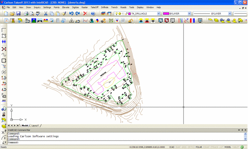
Now we can begin to process this drawing. The
main Takeoff commands are listed in processing sequence in the
Takeoff (or SiteNET in the Civil module) pull-down menu. Many of
these commands are also grouped as icons in the "Takeoff General"
toolbar shown here.


From the Takeoff menu, choose Drawing Cleanup. Typically, drawings have lots of drafting fixes that must be done before the surfaces can be modeled. This command will apply the selected cleanup functions on the drawing to help automate the cleanup. Here’s a brief description of the most important of these functions:
Remove Layers With No Entities: Drawings often have lots of layers. This routine removes layers that have no entities in the drawing so that we don’t have to deal with them.
Join Linework With Same Endpoints: This routine will take linework that is broken into multiple segments and join them into a single linework entity. For example, it will join together broken segments of a contour polyline into a single polyline.
Reduce Polyline Vertices: This routine removes extra vertices from polylines as long as the removing does not shift the polyline more than the specified Offset Cutoff. This will reduce the size and complexity of the drawing.
Set Elevation Outside Range To Zero: In case the drawing contains entities that are outside the range of valid elevations for the site, this routine will set them to zero elevation. The program treats zero elevations as “no elevation” and modeling will filter out these zero elevation entities.
For this site, the elevations are around 800. So let’s set the Min elevation to 500 and the Max elevation to 1000. The cleanup will set any entities outside this elevation range to zero. With other Takeoff functions, we can later assign proper elevations to any of these zero elevation entities that need to be used in modeling.

Once the Drawing Cleanup options are set as shown, pick OK. When the cleanup is done, the program will show a report of the cleanup results. Pick the Exit button to exit the report viewer.

From the Takeoff menu, choose Define Layer Surface/Material/Subgrade. Every entity (line, polyline, point, etc) in the drawing is assigned a layer name. Takeoff uses the entity layer names to define which entities are for the existing ground surface, the design surface or no surface. These surfaces are referred to as the “Target” surfaces. The drawing entities are assigned their target surface by their layer name. For example, if polylines representing design contours are on the layer “Final”, then “Final” will be set as a layer for the design surface. For layers of entities that are for neither existing nor design surfaces (such as text labels for street names), the layer target is set to Other.
The Define Layer Surface dialog has three lists of layers: Existing, Design and Other. To switch between lists, pick the tabs at the top of the dialog.In this drawing, all the contours are for the existing ground surface. In the layer list, all the layers that start with INDEX and INTER are for these contours. So highlight these layers and then choose Move To Existing. To highlight multiple layers at a time, hold down the keyboard Ctrl key while picking with the mouse.
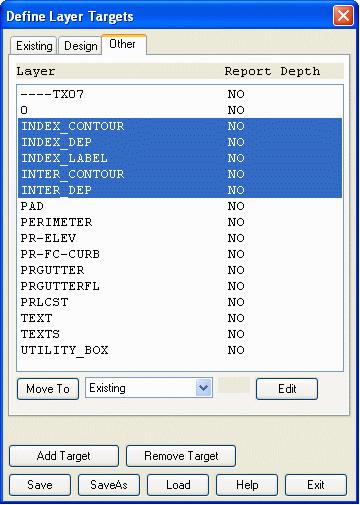
Next move the layer names that start with “PR” (for proposed) to the Design surface by highlighting these layers and choosing Move To Design. Also move the layer “PAD” to design.
Next pick the Save button to save our changes and then pick Exit.There are more tools for assigning layer surfaces. In the Display menu, you can turn on/off whether to display layer targets by using Existing Drawing, Design Drawing and Other Drawing. Practice turning on/off the Existing, Design and Other Drawing in the Display menu. When only Existing Drawing is on, you should see just the contours. When only Design Drawing is on, you should see just the design polylines and leader labels. When only Other Drawing is on, you should see the entities that are assigned to neither existing nor design.

Some of these layers we do want to assign to existing and design. To better see the entities, zoom in on them using the View->Window command and pick two points that make a window around the entities as shown. Once zoomed in, you can see a text label of “818.70 PAD” which is for the design surface. Labels “817.00”, “818.00” and “819.00” are contour labels for the existing contours. There are a few commands in the Inquiry menu to find out the layer names for these entities: List, Layer ID and Drawing Inspector. Let’s run the Layer ID command and pick the “818.70 PAD” label. At the Command line, it reports this layer is “----TX07”. Next pick the “818.00” label and it reports this layer is “TEXTS”. Now that we know these layer names, we can return the drawing view back by running View->Zoom->Previous and going to the Display menu and checking on Existing Drawing and Design Drawing.

Next run Define Layer/Material/Subgrade and pick the Other tab. Highlight “----TX07” and pick Move To Design. Then highlight “TEXTS” and pick Move To Existing.


Besides assigning target surfaces by layer, layers are also used to define material names and subgrades depths. By assigning material names and depths to layers, the volume, area, length and count for entities on these layers can be reported. Also the depth is used to vertically adjust the design surface. The polylines used for subgrade depth must be closed polylines. Takeoff supports nested subgrade polylines for exclusion areas such as islands by counting how many subgrade polylines surround an area. If the number is odd, then the area is inside the subgrade. Otherwise the area is not part of the subgrade.
First, we need to know the layer names for our subgrades. Go to the Display menu and check on Design Drawing, uncheck Existing Drawing and uncheck Other Drawing. Then run Inquiry->Layer ID and pick the large pad polyline. It reports that this layer is PAD. Next use Layer ID to pick the curb polyline. It reports that this layer is PR-FC-CURB.Next we need to make sure that these polylines are closed. In this example, the outside curb polyline is open at the top. To close the polylines, run Edit->Polyline Utilities->Edit Polyline->Close Polylines. Then pick each of the pad and curb polylines and press Enter when done selecting. Here are the Command line prompts:
Select Polylines to set closed.
Select objects: 5 found, 5 total
Select objects: (Press Enter)
5 polylines already closed.
Closed 1 polylines.
Now run Define Layer Target/Material/Subgrade and pick the Design tab. Highlight layer PAD and pick the Edit button. A dialog appears for defining the pad material properties. Check on the Include In Material Report option, enter the Material Name as “Pad”, set the first subgrade name to "Pad", and set the Depth as 1. Calculating cost is an optional feature. For this example, put in a Cost of "$15" Per "Ton" with a density of "110". Also, set the "3D Drive View" to Color and Red. Once the dialog is filled out as shown, pick OK.

Next pick layer PR-FC-CURB and choose Edit. In the Edit Materials dialog, check on Include In Material Report, set the Material Name to “Pavement”, set the first subgrade name to "Pavement", and set the Depth to 1.5. Then pick OK.
To save the subgrade changes, pick the Save button on the Define Layer Surfaces dialog. Then choose Exit.Now let’s visually verify the subgrade areas. In the Takeoff menu, run Subgrade Areas->Hatch Subgrade Areas. There is a dialog to select which subgrade to hatch. Choose the Pavement. Then there is a dialog for the hatch pattern and color. Click OK. Then run Hatch Subgrade Areas again. This time choose Pad and set the hatch pattern to Hex with green color. The resulting hatch areas show where the subgrade is applied. Notice how the islands are not hatched because they are curb polylines that are already inside another curb polyline. Also note that the smaller pad area is not hatched because this polyline layer is different than the bigger pad polyline. When finished viewing the subgrade areas, run Takeoff->Subgrade Areas->Erase Subgrade Hatches.

Takeoff will model the existing ground and design surfaces based on points, lines and polylines with elevation. It is essential for these drawing entities to have correct elevations in order to get correct surface models. Often the provided drawings will have the drawing entities at elevation of zero with text labels indicating the true elevation. Takeoff has many tools for assigning elevations to these entities.
To help visualize which entities need to be assigned elevation, Takeoff will color entities at zero elevation in grey. As entities get assigned elevation, they return to their original color. This elevation coloring is applied to layers that have been assigned to the existing or design surfaces.Let’s start by working on the existing
surface. To isolate the existing entities, go to the Display menu
and check on Existing Drawing, uncheck Design Drawing and uncheck
Other Drawing. In the Inquiry menu, there are commands for checking
elevations. To check the elevation of the contour polylines, run
the Inquiry->Drawing Inspector. Right click and make sure
Display Elevation is checked. Next, hover over a contour polyline
and Drawing Inspector will report the elevation. Other info may be
displayed as well depending on what is selected from the right
click options.
In this example, the existing ground surface is defined by just contour polylines and these polylines already have elevation. So there are no changes needed for preparing the existing surface entities. If the contour polylines were at zero elevation, then you could use the Elevate->Assign Contour Elevation commands.
Next let’s prepare the design surface. To isolate the design entities, go to the Display menu and check on Design Drawing, uncheck Existing Drawing and uncheck Other Drawing. Notice that all the design linework is greyed because it is at zero elevation. Run the List Elevation command and pick the main pad polyline. At the command line, it confirms that the elevation is 0.
To set the pad polyline elevation, run Elevate->Set Polyline To Elevation. Enter an elevation of 818.7 (based on the text label). At the Select objects prompt, pick the bigger pad polyline and press Enter.
New Elevation <0.0000>: 818.7
Select Lines, Arcs, Circles or Polylines for elevation change.
Select objects: (pick the pad polyline) 1 found
Select objects: press Enter
LWPOLYLINE
Number of entities changed> 1
Next let’s set the elevation of the smaller pad under the main pad. First, use View->Window to zoom in around the smaller pad so that we can read the text label. The label of “17.56” is short for 817.56. In this example, the 800 was dropped from many of the elevation labels to save on label clutter. Run Set Polyline To Elevation again. This time enter an elevation of 817.56 and pick the smaller pad polyline. Then run View->Zoom->Previous to get back to the full view of the site.

Finally, we need to set the elevations for the
curb polylines. First, use View->Window to zoom in around some
of the curb labels below the smaller pad. Then run Elevate->2D
to 3D Polyline->Text With Leader. This command will assign the
elevations from the labels to the polylines by following the label
leader to find the position on the polyline. For polyline vertices
without elevation labels, the elevations will be interpolated from
the other labels. Before processing, this routine prompts for
samples of the elevation label, the leader and the polylines to
convert. Then you can select all the entities in the drawing and
the routine will sort the labels, leaders and polyline by the
sample layers and assign the elevations.
 For this example, pick one of the labels with
a “TC” suffix as the elevation text sample. Then pick the leader
line for the annotation leader sample. Then pick the curb polyline
for the polyline to convert sample. At the Select objects prompt
for processing, type “all” to select all the drawing entities and
press Enter. For the elevation to add, enter 800 so that labels
like “17.81” get assigned as 817.81.
For this example, pick one of the labels with
a “TC” suffix as the elevation text sample. Then pick the leader
line for the annotation leader sample. Then pick the curb polyline
for the polyline to convert sample. At the Select objects prompt
for processing, type “all” to select all the drawing entities and
press Enter. For the elevation to add, enter 800 so that labels
like “17.81” get assigned as 817.81.

Next a dialog appears for selecting which
labels names to use. When Takeoff detects different text labels
within the elevation labels, you need to choose which ones to
process. In this case, we only want the labels with "TC". So
highlight TC, pick Add and then pick OK.
Select sample of elevation text: pick label
Select sample of an annotation leader: pick leader line
Select sample of a polyline to convert: pick curb polyline
Select polylines to convert, leaders and elevation labels to process.
Select objects: all
Select objects: press Enter
Joining adjacent polylines...
Reading the selection set ...
Enter elevation to add to label values <0.00>: 800
Pre-processing entity #420 of 420
Processing leader #141
Remaking polyline #4
All the curb polylines now have elevations.
Now run View->Zoom->Previous to return to the full site view. The design polylines should now have colors because the elevations are assigned.The limits of the site are defined by a closed polyline. This polyline is used as the boundary for the models and the volumes. In this example, there is a closed polyline on the PERIMETER layer. The layer target for this layer is Other. Go to the Display menu and check on Other Drawing so that the perimeter is displayed. Then run Takeoff->Boundary Polyline->Set Boundary Polyline and pick the perimeter polyline. This selected polyline is now set as the boundary polyline for the rest of the Takeoff routines.

To calculate volumes, Takeoff needs two surfaces: existing ground and design. These surfaces are modeled by triangulation. With the preparation of the previous steps, we’re now ready to make the models. The drawing entities have been cleaned up, assigned elevations and assigned target surfaces by layer. Making the models is now a one step process. To make the existing ground surface, run Takeoff->Make Existing Ground Surface. The program will process the entities and make the triangulation surface. Then to make the design surface, run Takeoff->Make Design Surface.
As a visual check that the design surface modeled correctly, let’s run the Takeoff->3D Drive Simulation command. This routine shows a 3D view of the site and allows you to drive around. This is a good way to check that the surface modeled correctly. We want to make sure that there are no elevation spikes and that the subgrade depths are modeled. To drive the site, choose a View Direction, View Position and Vehicle. Then pick the Run button and use the arrow keys to turn. Pick the Stop button to pause the moving. You can also try the Surface Shading options for different views of the surface. When done with the 3D Drive Simulation, pick the Exit button (Arrow with door image).

Cut/Fill color maps can be used for a visual
output of the site cut/fill areas and also serves as another check
that the models are correct. In the Display menu, choose Cut/Fill
Color Map. Cut areas are drawn in different shades of red for
different depths of cut while fill areas are drawn in blue. Also
under Display, check on Cut/Fill labels.
To change the size, color, spacing and further label options, run
Display->Display Options and go to Cut/Fill Labels tab shown
below. The resolution of the color blocks in the map can be changed
in the next tab with Cut/Fill Color Map Subdivisions. This
parameter is the number of rows and columns of color blocks to
create. To turn off the color map, go to the Display menu and pick
Cut/Fill Color Map to uncheck it.

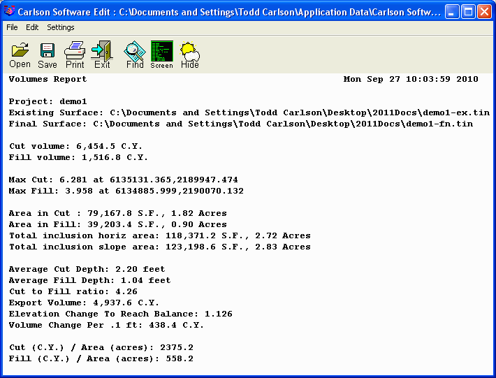
To calculate volumes, run the
Takeoff->Calculate Total Volumes command. There is an options
dialog for setting the cut swell factor and fill shrink factor.
These values get multiplied into the cut/fill volumes. Set these
factors as desired and click OK. Then the routine calculates the
volumes and display the report which includes the cut/fill volumes
and areas. The report can be printed or saved to a file. Pick the
Exit button to exit the report viewer. Run the command again and
change the "Report Output" mode to see the volumes in different
formats like PDF or Excel.

To report the quantities, run the
Takeoff->Material Quantities->Standard Report routine. There
is the option to only report selected entities as well as the
ability to report material quantities that may extend beyond the
boundary polyline.
 The report includes the count, length, area and
volume for each type of material that was assigned for reporting in
the Define Layer Target/Material/Subgrade command. The Material
Quantities->Custom Report routine can be used to reporting these
values with control of the report format and the option to export
to Excel.
The report includes the count, length, area and
volume for each type of material that was assigned for reporting in
the Define Layer Target/Material/Subgrade command. The Material
Quantities->Custom Report routine can be used to reporting these
values with control of the report format and the option to export
to Excel.
