Geodetic Reports
In this lesson you will create a geodetic report containing both
local and Grid coordinates from a survey based on an assumed local
datum. The plan geometry will be annotated with both ground and
grid distances. this is useful when a survey has been performed on
with assumed coordinates and elevations but must be reported in
Grid coordinates or is instances where both ground and grid
coordinates need to be reported.
1. From the Desktop, Launch Carlson by
clicking on the Carlson Icon
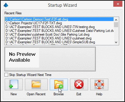
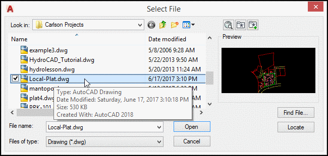
2. Click Browse and select the supplied
drawing Local-Plat.DWG
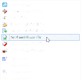
3. From the Points menu, select Set
Coordinate File and select the supplied file
Local-Coord.CRD.
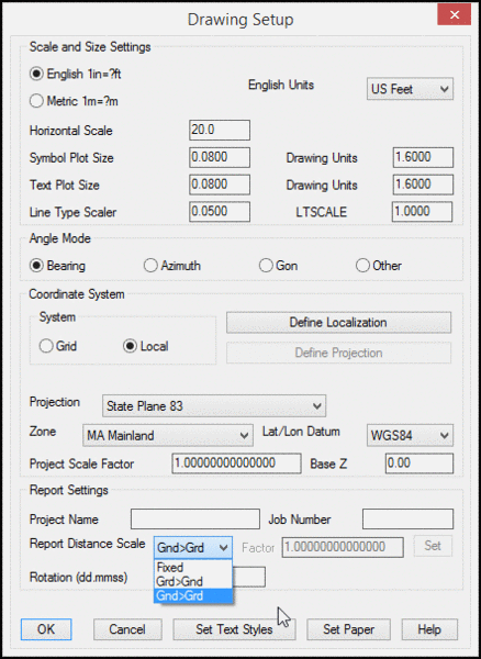
4. From the Settings pull down
menu, select
Drawing Setup
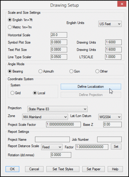
5. Set the Projection to
State Plane 83 and select the MA Mainland Zone
6. Select Define Localization
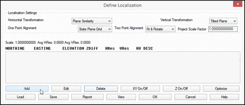
7. Click Add to enter
points for defining the localization to grid coordinates
8. Add the point and coordinate information for
points 56 and 52 by entering the point numbers and
their respect Grid Coordinates.
These 2 points were located via RTK GPS to establish grid
coordinates.
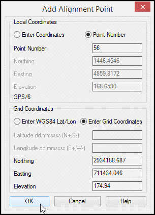
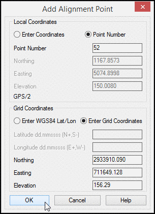
9. Click OK after each
entry.
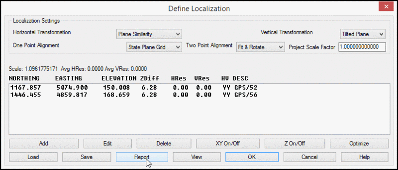
10. Ensure that the XY
ON/OFF and Z ON/OFF toggles are set to Y for
yes.
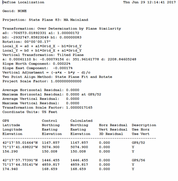
11. Back in the Define Localization dialog box,
click Report
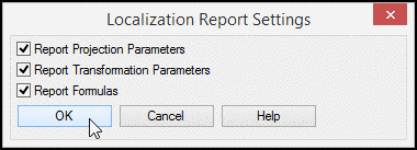
11. Ensure all report options
are enabled and click OK
The localization report is displayed.
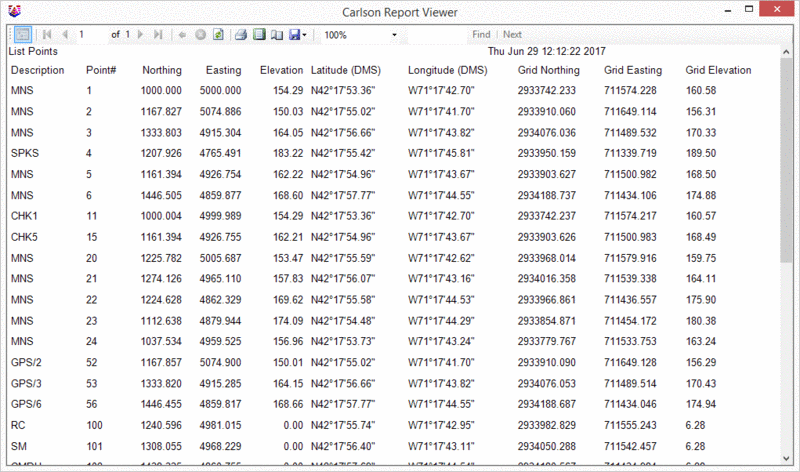
12. From the Points pull down menu, select List
Points
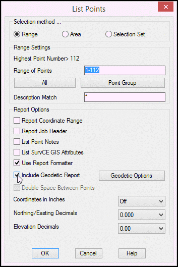
13. Enable the Use
Report
Formatter and Include
Geodetic Report options.
14. Click
OK.
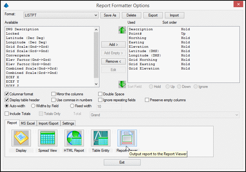
15. In the Report Formatter
options dialog box, select the desired Available fields to the left
and click Add to move them to the Used fields on the right.
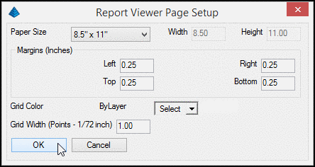
16. Select Report Viewer
Note: To further control the report by adding user attributes,
additional fields, Headers and Subheaders, Fonts etc., Use the
Settings Tab in the previous step.
Both local and grid coordinates are displayed.
18. Return to the Drawing Setup as in step 4
19. Set the Report Distance Scale option
to GND>GRD for ground to grid distances.
20. Click OK
21. From the Annotate pull down menu, select
Annotate Defaults
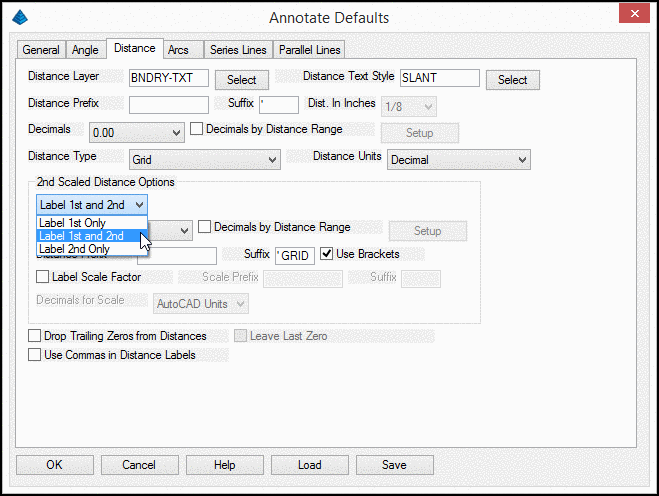
22. In the Distance Tab, set the 2nd Scaled
Distance Options to Label 1st and 2nd.
23. Add the Suffix 'GRID and enable the
Use Brackets option.
24. Click OK
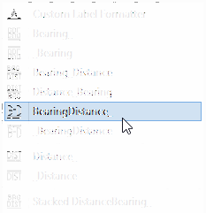
25. From the Annotate pull down menu,
select the Angle/Distance flyout then BearingDistance_
26. In the drawing, select the
most northerly property line of the parcel.
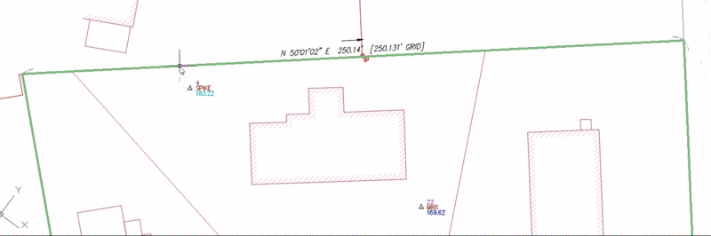
Both the ground distance and the projected scaled
distance are labeled