Cut Sheet
In this lesson you will create a Cut Sheet report for staking
grade for a proposed parking lot. you will open a supplied drawing
containing existing and proposed contours, a design surface, a
centerline file for the proposed curb line and points staked in the
field on a 1 foot offset line.
1. From the Desktop, click the
Carlson Icon to launch Carlson.
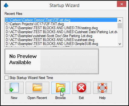
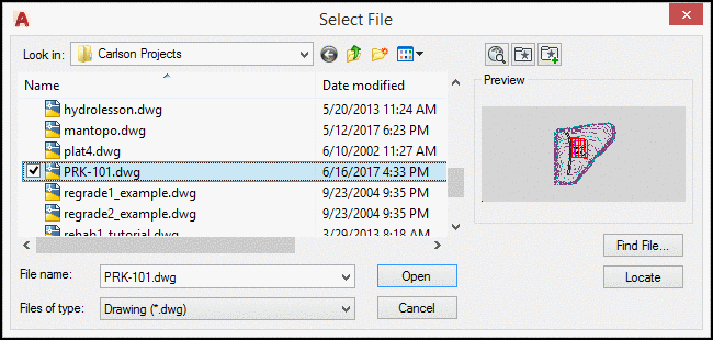
2. Click Browse and select the drawing
file PRK-101.DWG.
3. Click Open.
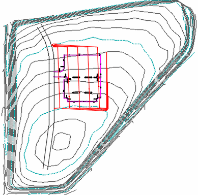
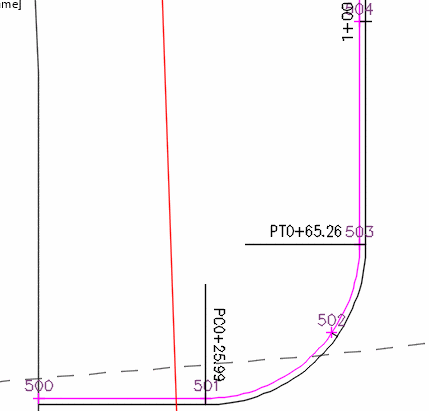
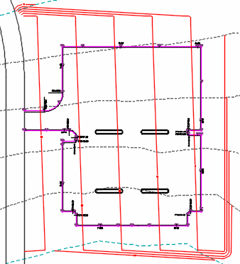
The drawing contains existing contours and a
proposed parking lot. A closer examination will reveal that the
outside curb line has been defined as a centerline (PRK-101 BK
Curb.CL) file.
See Centerline in the Help Menu or the tutorial on Basic Road
Design on creating centerlines.
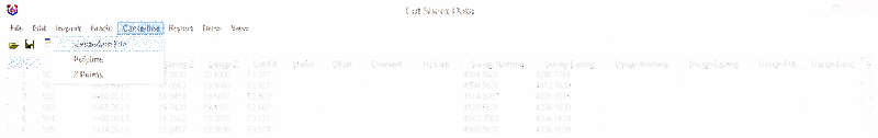
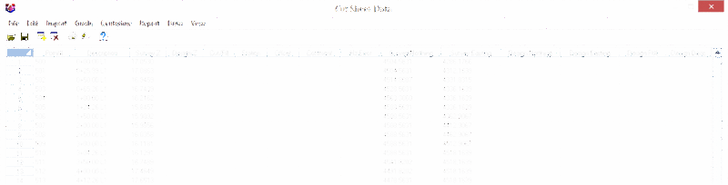
4. From the Survey pull down menu select
Cut Sheet
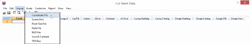
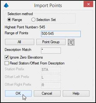
5. Click Import and select the
option Coordinate File.
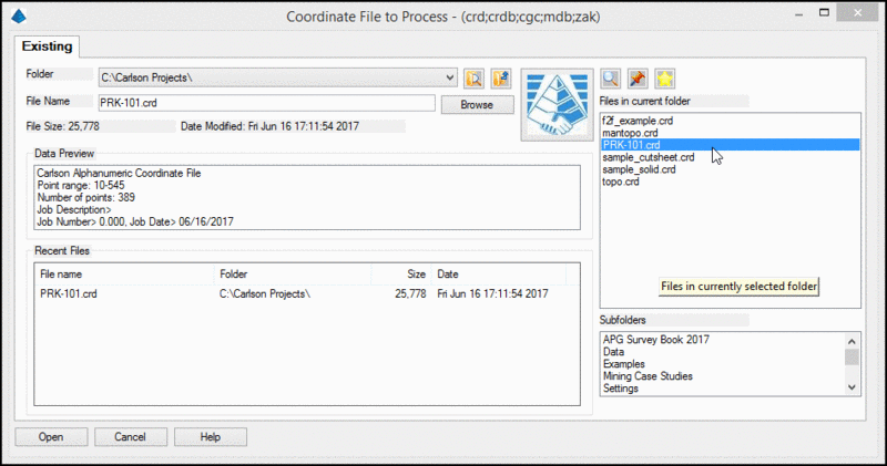
6. Select the coordinate file
PRK-101.CRD and click Open.
7. Ensure that the selection method
is set to Range and the Range of Points to 500-545.
This file also contains original ground
points
8. Click OK
The points 500-545 are field located points along the 1
foot offset line to the proposed curb at the original ground grade.
These points can be collected and stored in the field using
SurvCE/PC.
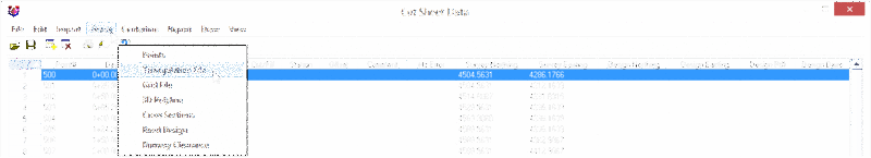
9. From the menu line, select Grade then
Triangulation File
This process will select a design surface model for the
proposed grades. Note the additional methods of determining the
proposed grades.
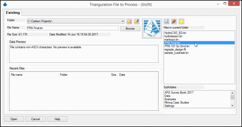
10. Select the file PRK Final.TIN and
click Open.
The DesignZ elevation field is populated from the
proposed TIN and a Cut/Fill amount is calculated.
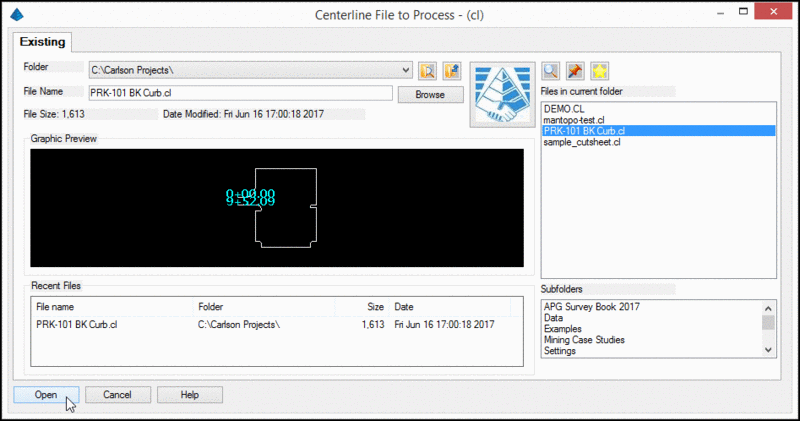
11. From the menu line select Centerline
then Centerline File.
12. Select the file PRK-101 BK Curb.CL and
click Open.
The Cut Sheet now contains the station and offset information for
the curb line.
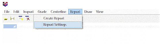
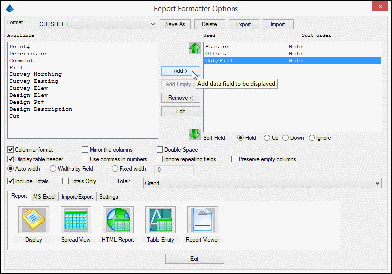
13. From the menu line, select Report then Report
Settings.
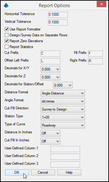
14. Ensure the Report Options are set as shown
above and click OK.
15. From the menu line, select Report then
Create Report.
16. Select the desired
Available fields on the left and click Add to move them to
the Used fields on the right.
For this lesson, just select Station, offset and Cut/Fill to create
a simple cut/fill report.
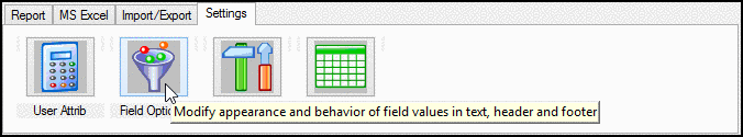
17. Select the Settings Tab and click
Field Options.
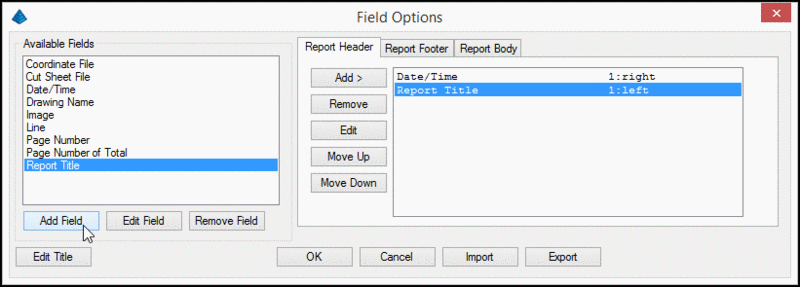
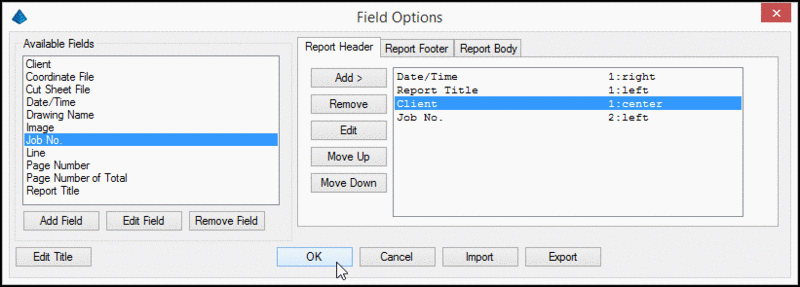
18. Similar to above, Select the desired
Available fields on the left and click Add to move them to
the fields on the right in the Report Header Tab.
19. To create user defined additional
fields to include in the report, click Add Field.
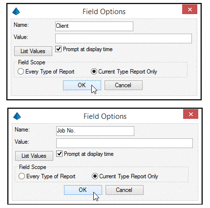
20. Create 2 new fields named Client and
Job No. making sure to enable the Prompt at display time.
This will cause the program to pause for user input at the time of
creating the report. Note the option to create fields for this
current type of report only or every type of report.
21. As shown above, move the new fields to the
Report Header Tab.
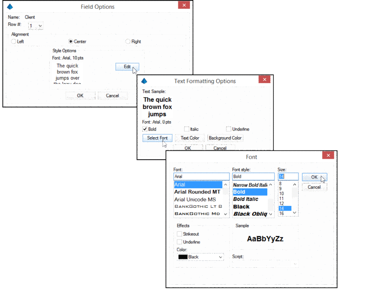
When the fields are moved, you will be prompted to select various
format options.
22. Set the following fields:
- Client field to Row #1, Center justified, Bold Font with
a 14 pt text size.
- Job No. Field to Row #2, Left justified, regular font
with a 10 pt text size.
23. Click OK
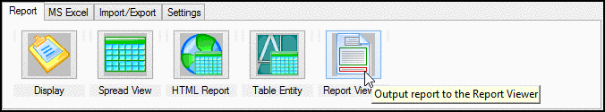
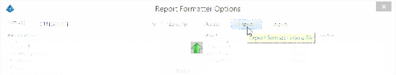
24. Back in the Report Tab, Select Report Viewer
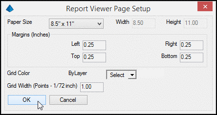
25. Select an 8.5"x11" paper size with 0.25
margins all around the click OK
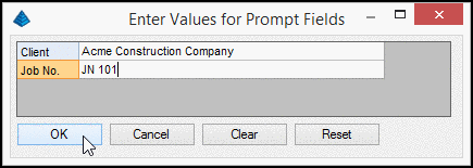
26. Enter the values for the Prompt Fields in the
dialog box, then click OK
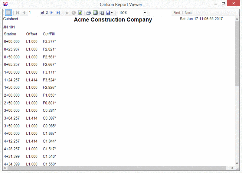
The resulting report is displayed which can be printed or exported
to various formats. The above process can be repeated for any
number of fields and saved as an .FMS file for future use or
to develop company or client report standards.
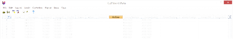
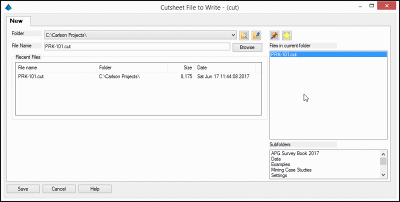
27. Back in the main Cut Sheet Data spread sheet
editor, click Save and save the file as
PRK-101.CUT
This ends Lesson 22: Cut Sheet