3D Drive Simulation
This command allows you to view and move around the design surface
in 3D mode.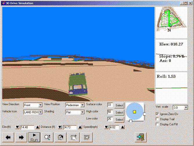 Use the arrows on your keypad to
move around the drawing.
Use the arrows on your keypad to
move around the drawing.
At the very bottom of the window you will find the basic commands:
Run will start to drive your vehicle around the surface, once your
vehicle is moving the Run button turns into the Stop button. The
arrows moves your vehicle left and right. The magnify glass zooms
in and out. Click and drag up to zoom in and click and drag down to
zoom out. When your vehicle is stopped the  icon can be
used to rotate the vantage point of the viewer by the x, y, or z
axis. When you move the cursor to the screen it will change into a
x, y symbol or a z symbol. Move the cursor around to move it from
one to the other. If you have the x, y cursor move right or left to
change the x axis view, or to change the y move the cursor up or
down. If you have the z cursor than move it in a circular fashion
to rotate the view point according to the z axis.
icon can be
used to rotate the vantage point of the viewer by the x, y, or z
axis. When you move the cursor to the screen it will change into a
x, y symbol or a z symbol. Move the cursor around to move it from
one to the other. If you have the x, y cursor move right or left to
change the x axis view, or to change the y move the cursor up or
down. If you have the z cursor than move it in a circular fashion
to rotate the view point according to the z axis.
The hand icon allows you to pan around the viewer. Click and drag
the direction you want to move. The  icon
toggles the shading of the surfaces. The
icon
toggles the shading of the surfaces. The  icon exits
3D Driver Simulation.
icon exits
3D Driver Simulation.
Above the basic command buttons you can change the Elevation and
Distance away from your vehicle. Also, you can set the speed at
which your vehicle travels. For a smaller drawing you may want to
move around slower, for a larger drawing faster. Note: Unrealistic
speeds such as 500 mph in a dozer may cause 3D Drive Simulation to
freeze.
View Direction: Sets the direction of the view from the Front,
Back, Left, or Right.
Vehicle Icon: You can select which Vehicle you want to use whether:
Dozer, Hummer, School Bus or none at all.
View Position: Sets the elevation and distance to either that of
the driver, a pedestrian, or bird.
Shading: Here you can set the shading of the surface to either
Flat, Smooth, Elevation, Cut/Fill, or none. Flat just shades the
contours as they are. Smooth smooths contours to look for
realistic. Elevation colors different elevations in different
colors so differences can visual be seen. Cut/Fill colors areas of
cut differently than areas of fill so they can be visually seen.
None merely shows the triangulation and does not shade in a
surface.
You can select the Surface, High, and Low color by enter in an
AutoCAD defined color number or you can choose Select to pick a
color. The circle on the right determines the shade of the
color.
In the top right of the 3D viewer is an aerial map of your surface.
Below that the Elevation, Slope percentage, Azimuth, and Roll are
updated as your vehicle moves around the surface. Slope and Roll
are shown visually here as well.
On the bottom right you can set the Vertical Scale and check to
Ignore Zero Elev, Display Trail, and Display Cut/Fill. If you
increase the Vertical Scale than elevation differences can be seen
easier. Ignore Zero Elev does not display elevations of zero in the
3D viewer. Display Trail draws a line where your vehicle has
driven. Display Cut/Fill displays the cut and the fill.
Prerequisite: a design
surface
Keyboard Command: tk_flyby