Define Layer Surface/Material/Subgrade
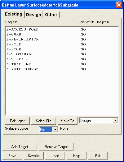
The Define Layer Surfaces dialog box (shown here) offers many
functions that will ultimately make up the surface models used in
volume and material calculations. Every entity (line, polyline,
point, etc) in a drawing is assigned a layer name. Carlson Takeoff
uses the entity layer names to define which entities represent the
existing ground surface, the design surface or no surface. These
surfaces are referred to as the "Target" surfaces. Any previously
created triangulation file (.tin) can be set to the design or
existing Target with the Surface Source drop-down set to File. In
this mode, the Select File button will allow you to pick the .tin
file you want to use for the Target.
When the Surface
Source drop-down is set to Layers, drawing entities are assigned to
target surface by their layer name. For example, if
polylines representing design contours are on the layer "Final",
then "Final" will be set as a layer for the design surface. For
layers of entities that are for neither existing nor design
surfaces (such as text labels for street names), the layer target
is set to Other. The Define Layer Surfaces dialog has three lists
for layer targets: Existing, Design and Other. To switch between
lists, pick the tabs at the top of the dialog. To move a layer to a
target destination, highlight the desired layer, choose the target
from the Move To list and pick the "Move To" button. All layers
populate the "Other" target before being assigned to "Existing" or
"Design".
Besides the basic three layer targets (Existing, Design and Other),
you can add more target surfaces with the Add Target button. When
another target is defined, there will be another tab along the top
of the Define Layer Surfaces dialog. Then layers can be assigned to
this additional target surface. The only pre-defined additional
surface is Overexcavate. The layers that are assigned to the
Overexcavate target can be modeled into the Overexcavate surface
using the Make Overexcavate Surface command. Besides Overexcavate,
the other additional targets are user-defined. The layer targets
can be modeled using the Make User-Defined Surface command. Then
these surfaces can be used in Takeoff commands by assigning them to
a Takeoff existing or design surface using the Set Active Surfaces
command.
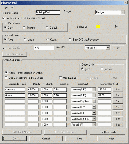
Edit Materials
The "Edit" button activates the Edit Material dialog box (shown
here) and allows you to define the Material name and Subgrade
depths and names. Besides assigning target surfaces by layer,
layers are also used to define material names and subgrades depths.
By assigning a material name, Subgrade names and depths to layers,
the volume, area, length and count for entities on these layers can
be reported. Also the depth is used to vertically adjust the design
surface, or tie into the design surface by a Slope Ratio if "Use
Layback" is checked on. For Area
and Back Of Curb/Pavement material types, the polylines on the
layer used for a Material must be closed polylines. Carlson
Takeoff supports nested Subgrade polylines for exclusion areas such
as islands by counting how many Subgrade polylines surround an
area. If the number is odd, then the area is included in the
Subgrade. The even count regions in the area are not part of the
Subgrade. To activate the Edit Material, select a layer from the
list and then choose "Edit".
Include in Material Quantities Report
With this option checked on, the material that is named will appear
in the Material Quantities Report. The report will include either
the area of the material, the linear length of the material, or the
number of items counted on the layer defining the material. This is
accomplished by choosing "Area", "Linear", or "Count" for the
Material Type.
3D Drive View
This option allows you to assign a color or texture for this
particular material for display purposes during the 3D view/drive
simulator. The color is assigned to the design surface TIN
file.
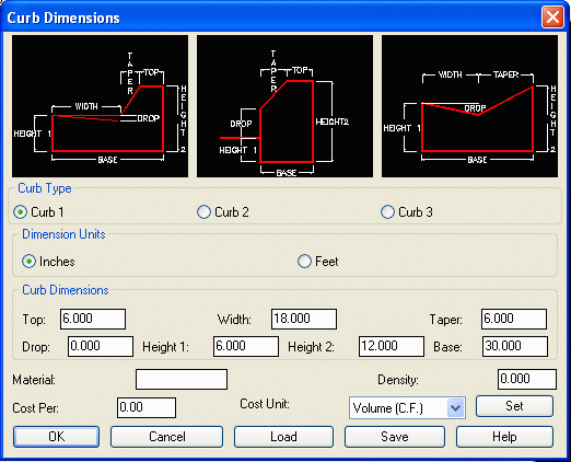
Material Type
This will report the subgrade by area, linear length, count, or as
curb/pavement area. If you choose Back of Curb/Pavement then you
can pick on the Curb Dimensions button and bring you to the below
dialog:
With the Back of Curb/Pavement, the 3D polylines represent the back
of curb elevations. When using this method, the curb polylines
alone define the pavement areas and no other design entities (ie.
design contours or spot elevations) should be in the pavement area.
The program will adjust the design surface for the height of the
curb above ground to get the elevations to the top of pavement.
Also with Curb/Pavement, the program will calculate your curb
volume as well as act as the limit of the pavement. For the
pavement areas bounded by the curb polylines, the program will
apply the subgrade depths defined separately from the Curb
Dimensions. These pavement subgrade depths are defined in the Area
Subgrades section of the Edit Material dialog. The pavement limit
will be from the Back of Curb polyline offset by the length of the
Curb base. In the above case the base is 30 inches wide. Therefore,
the pavement area will stop 30 inches before the Back of Curb
polyline.
Material Cost Per Cost Unit
Use this field to add the value of the multiplier for the unit cost
of your material. If the material type is an area that has multiple
subgrades, use the available fields below to add each individual
subgrade name, depth and cost value per unit type. If a linear or
count type material type option is selected, use the "length in
feet", or the "count" unit options.
Adjust Design Surface by Depth
This determines whether the subgrade depths are
incorporated in the design surface or not.
Use Vertical from Pad to Surface
This will interpolate the surface model out to your layer and then
vertically adjust the model to tie into the layer. With this
checked off, the program will directly interpolate a surface model
between your layer and the elevated entities around it.
Area Subgrades
Depth Units
Select the "feet" or "inches" as the unit value desired for depth
of subgrades.
Subgrade Name Depth Shrink Cost
Per Cost Unit Density
Use these options for areas that are represented with a
single/multiple closed polygon/polygons in the drawing, but have
multiple material types defining the surface. Simply name each
"lift" in the area, issue a depth value and add a cost unit if
desired, or click on select and choose a material from the
Materials Library (see Define Materials Library for more). Carlson
Takeoff will report each subgrade material value in the material
quantities report. The Shrink factor is multiplied by the subgrade
volume in the material quantities report and represents the fill
shrinkage. A Density factor can be entered in when using Cost Per
Tons.
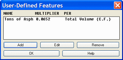
If user entered values are needed in the report use the "Edit
User-Fields" button to activate the "User Defined Features" dialog
box shown here. Choose the "Add" button to define needed fields
such as TONS of material or BAGS OF GRASS SEED for reporting
options.
Once all of the material subgrades, depths and cost units or user
defined units have been defined, select save to preserve the
settings in a .trg file, the "save as" function allows the user to
name the file to load later.
Prerequisite: None
Keyboard Command: define_tk_layers