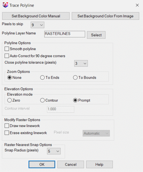
Pixels to skip:
Sets the number of
pixels (0-25) that
Trace Polyline will "skip" (pass over) in
order to connect two groups of pixels of the same color. This
allows for longer length polylines to be created on poor quality
images that contain gaps in between traceable line work. A larger
number of pixels to skip will typically create longer length CAD
line work. However, if the image line work contains few gaps, then
the
Pixels to skip should be set lower to avoid incorrectly
connecting traced line work between unrelated traceable line
work.
Smooth Polyline:
Interpolates between nodes of the polyline currently being traced
to create interstitial nodes in the current polyline that give the
current polyline a smoother appearance.
Auto-correct for 90 degree corners:
Attempts to determine if a section of line work represents a 90
degree corner. If so, creates a 90 degree corner in the current
polyline traced over line work.
Close polyline tolerance (pixels):
Sets the close polyline distance tolerance (in pixels, 0-25) for
Trace Polyline. If the beginning and end of the current
polyline are closer than the close polyline distance tolerance then
Trace Polyline will determine the current polyline to be
closed, geometry will be automatically added to the poyline to
connect the beginning and end of the polyline. Any redundant nodes
created by connecting the beginning and end of the polyline will be
removed.
Zoom Options:
1. To Ends, zooms view to the end nearest the most recently
added polyline geometry. This end is set as the currently active
end (see
switch ends).
2. To Bounds, zooms view such that the entirety of the
geometry of the currently traced line work is visible.
3. None, view does not change after the addition of new
geometry.
Elevation Options:
1. Contour, sets polyline geometry z values based on
elevation set by the
contour prompt. When enter is pressed,
or the currently active polyline is closed, the user is prompted to
update contour information (again, using the
contour
prompt).
2. Prompt, prompts user to enter z value of traced polyline
geometry. If enter is pressed or polyline is closed, user is again
prompted to enter z value of traced polyline geometry.
3. Zero, all polyline geometry is drawn with its z value set
to 0.0.
Modify Raster Options:
1. Draw new
linework, Draws a 1 pixel wide line of the color of the current
line work on the "current" image.
2. Erase existing linework, Sets pixels on "current" image
to the current background color up to a distance of 'Pixel size'
from the current polyline geometry.
Raster Nearest Snap Options:
Snap Radius, tolerance factor for selecting line work. If line work
is found at a distance less than 'Snap Radius' away from most
recent user selected pick point, that line work will be added
to the geometry of the current polyline.
Prompts:
Pick segment or [Options/Manual point/cross line
Pick/Undo/Close/Switch active end/Exit] (Enter to end
polyline):
(Select pick point to continue tracing
polyline.)
(O)-Options, opens the Trace Polyline
options dialog.
(M)-Manual point, allows user to contribute additional geometry to
current polyline manually, ie not automatically traced.
(P)-cross line Pick, allows user to select pick point by crossing
line work to be added with a cross line.
(U)-Undo, undoes previously drawn geometry.
(S)-Switch active end, switches the end to which geometry will be
added (given new geometry begins near active end).
(E)-Exit, exits
Trace Polyline.
*(C)-Continue, if no geometry has been traced, continue allows user
to select on screen polyline geometry and use that as the basis for
new line work.
Pick manual point or [enable snap Nearest/Switch active
end/Exit] (Enter to end):
(Pick manual point to add to polyline geometry.)
(N)-enable snap Nearest, see
raster Nearest Snap
Options.
(S)-Switch active end, switches the end to which geometry will be
added.
(E)-Exit, exits
Trace Polyline.
Enter elevation or [Increment 1.00/Direction +/Exit] Elevation
<0.00>:
(Enter elevation in contour mode.)
(I)-Increment, increment the elevation according to "direction"
(either + or -).
(D)-Direction, toggles incremental direction from + to - or vice
versa.
(E)-Exit, exits
Trace Polyline.
Enter elevation or [Exit] Elevation
<0.0>:
(Enter elevation in Prompt mode.)
(E)-Exit, exits
Trace Polyline.