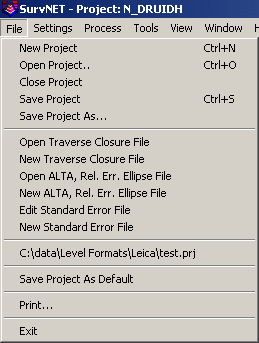
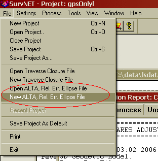
Selecting the File menu opens the following menu:
A Project (.PRJ) file is used to store all the settings and files necessary to reprocess the data making up the project. You can create a New project, or Open an existing project. It is necessary to have a project open in order to process the data.
The Save Project As Default can be used to
create default project settings to be used when creating a new
project. The current project settings are saved and will be used as
the default settings when any new project is created. Project
settings are covered in the Settings menu sections.
Some statutes and jurisdictions still require the computation of traditional traverse closures. SurvNet gives the surveyor the ability to compute the closures of multiple traverses within a project as part of the preprocessing of the project raw data. Closures for single or multiple traverses can be computed for a single project. Additionally, GPS closures can be computed for GPS loops. To compute closures you must first create a "Closure" file (.CLS). Closure files define the type of traverse loops that are to be computed and the point numbers that make up the traverse.
There are two options in the FILE menu that are used to create and edit the closure, .cls, files:
Open Traverse Closure File
New Traverse Closure File
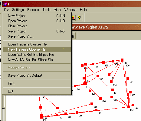
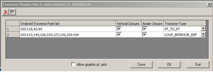
After choosing the 'New Traverse Closure File' you will be prompted for a new file name. After choosing a file name the following dialog box is displayed.
First enter the point sequence which defines the traverse in the bottom left edit box. Check the bottom check boxes to set whether vertical closure and angle closures need to be computed. Then choose what type traverse is being entered. When the bottom fields are correct press the 'Add' button and the traverse will be entered into the upper list box.
If you need to edit one of the traverses in the top list box mouse click the traverse to be edited. The fields will be entered in the lower edit fields. Make the appropriate edits, then click the 'Change' button to save the changes to the upper list box.
Enter the points that define the traverse. Points can be entered in the form:
1,23,30-35,45,23,1
A comma separates the point numbers. You can select a range (30-35)
when the points are sequential. You must start with the first
backsight point number and end with the last foresight point
number. For example, if you have a simple loop traverse with
angle closure using points 1, 2, 3 and 4, it will be entered as
"4,1,2,3,4,1" where 1 is the first occupied point and 4 is the
initial backsight.
You can turn the "Angle Closure" ON or OFF. If the angle closure is
ON, you will be shown the total angular error and error per angle
point. If the final closing angle was not collected you can turn
"Angle Closure" OFF and only the linear closure will be
computed.
You can turn the "Vertical Closure" ON or OFF. If the vertical
closure is ON, you will be shown the total vertical distance
closure.
In order to calculate the traverse closure, you must select the
TRAVERSE TYPE. It can be:
Pt. to Pt. Trav. - A point to point traverse is a traverse
that starts at a set of known coordinates and ends at another known
coordinate. This option assumes you start from two control
points and tie into two control points if an angle closure is
desired and one control point if only a linear closure is desired.
The first backsight distance and last foresight distance are not
used in computing the linear closure. Following is an example.
100,101,2-5
In the above pt. to pt. list Pt 100 is the starting backsight point, Pt. 101 is the starting instrument point. Pt. 4 is the ending instrument point and the foresight to the angle closure point is point 5. If a closing angle was not collected the list would look as follows '100,101,2-4'.
Loop Trav., Int. Az. Ref. - A closed loop traverse that begins by backsighting the last interior point on the traverse. Following is an example.
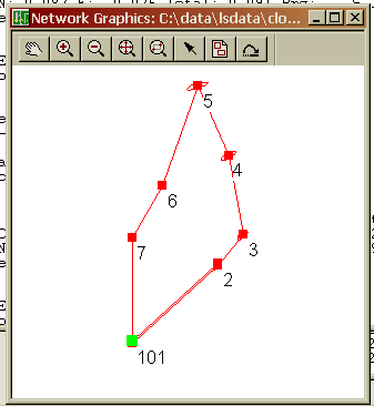
7,101,2-7,101
In the above example closed loop with angle balance list, point 7 is the backsight point and point 101 is the first occupied point. If the closing angle 6-7-101 was not collected the list would be entered as follows ' 7,101,2-7'
Loop Trav., Ext. Az. Ref. - A closed loop traverse that begins by backsighting an exterior point (point not on the traverse).
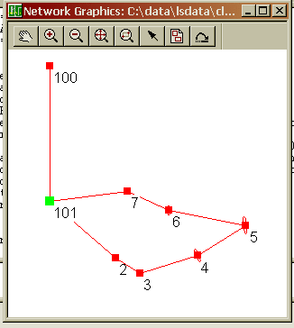
100,101,2-7,101,100
In the above example loop with exterior reference and angle balance list, point 100 is the backsight point and point 101 is the first occupied point. If the closing angle 7-101-101 was not collected the list would be entered as follows ' 100,101,2-7,101'
GPS Loop Closure: - GPS loop closures can be computed using this option.
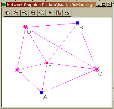
A,E,F,A
In the above example GPS loop, closure will be computed from the
GPS loop going from A-E-F-A.
GPS Point to Point Closure: - GPS
Point to Point closures can be computed using this option.
A,E,D,B
In the above example the closure will be computed from the GPS
traverse going from A-E-D-B. The starting and ending points MUST be
control points.
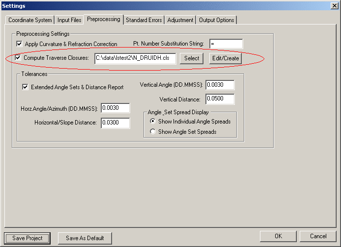
After the closure, .CLS, file has been created the preprocessing project settings need to be updated to include the closure file in the project. Following is a view of the settings screen that defines a closure file to be used in preprocessing. Notice that the check box 'Compute Traverse Closure' is checked and a closure file has been entered in the edit box field. Notice that the 'Edit/Create' button can be used to edit an existing closure file or create a new closure file.
When the data is
processed, the closure reports will appear in the RPT and ERR
files. You will notice that two closures are shown, one with no
angle balance and one with angle balance.
Following is an example of a closed loop traverse report:
Traverse
Closures
=================
Traverse points:
103-118,43-44
Traverse starting and ending on different points;
Compute angle closure.
Compute vertical closure.
BS
IP
FS
Angle FS H.
Dist. FS V. Dist.
103
104
105
173-07'48.5"
310.4921 -7.7483
104
105
106
167-48'21.5"
253.4875 5.6291
105
106
107
200-52'46.0"
381.4923 8.4877
106
107
108
149-09'05.5" 410.5476
-16.6830
107
108
109
080-42'36.5"
245.5731 9.4221
108
109
110
174-21'17.5"
175.3848 -5.6971
109
110
111
201-42'21.5" 367.0019
-11.8161
110
111
112
171-52'54.5"
237.7809 7.5346
111
112
113
192-32'53.5"
368.8402 -7.0329
112
113
114
171-30'59.0" 338.0028
-19.1945
113
114
115
184-54'03.5"
344.5010 16.3157
114
115
116
149-20'19.5"
353.8460 7.5562
115
116
117
202-19'01.5"
390.1123 -9.9180
116
117
118
112-36'32.0"
293.9935 2.0060
117
118
43
146-06'36.5"
411.3680 -7.7112
118
43
44
270-04'01.5"
Closing
Az: S
47-39'47.8"W
Computed Closing Az: S 47-39'51.3"W
Total angular error: 000-00'03.5"
Angular error per point: 000-00'00.2"
Correct Ending Coordinates, North: 1400952.0140 East:
2241884.7010
Ending Coordinates, North: 1400951.7936 East: 2241884.8160
Error, N: -0.2204 E: 0.1150 Total: 0.2486 Brg: N
27-33'06.7"W
Distance Traversed: 4882.4241 Closure: 1: 19643
Correct Ending Elevation: 948.1710
Ending
Elevation:
948.1203
Elevation
Error:
-0.0507
Closure After Angle Adjustment
103
104
105
173-07'48.3"
310.4921 -7.7483
104
105
106
167-48'21.3"
253.4875 5.6291
105
106
107
200-52'45.8"
381.4923 8.4877
106
107
108
149-09'05.3" 410.5476
-16.6830
107
108
109
080-42'36.3"
245.5731 9.4221
108
109
110
174-21'17.3"
175.3848 -5.6971
109
110
111
201-42'21.3" 367.0019
-11.8161
110
111
112
171-52'54.3"
237.7809 7.5346
111
112
113
192-32'53.3"
368.8402 -7.0329
112
113
114
171-30'58.8" 338.0028
-19.1945
113
114
115
184-54'03.3"
344.5010 16.3157
114
115
116
149-20'19.3"
353.8460 7.5562
115
116
117
202-19'01.3"
390.1123 -9.9180
116
117
118
112-36'31.8"
293.9935 2.0060
117
118
43
146-06'36.3"
411.3680 -7.7112
118
43
44
270-04'01.3"
Closing
Az: S
47-39'47.8"W
Computed Closing Az: S 47-39'47.8"W
Total angular error: 000-00'00.0"
Angular error per point: 000-00'00.0"
Correct Ending Coordinates, North: 1400952.0140 East:
2241884.7010
Ending Coordinates, North: 1400951.7739 East: 2241884.8363
Error, N: -0.2401 E: 0.1353 Total: 0.2756 Brg: N
29-24'26.1"W
Distance Traversed: 4882.4241 Closure: 1: 17715
Following is an example of a GPS loop closure report:
Traverse Closures

=================


GPS Loop Points:

A,E,F,A


GPS Loop Closure;


  Misclosure, X:  -0.0323   Y:  -0.0162   Z:  -0.0105

  Closure error:    0.0376   Perimeter: 20229.3858

  Precision: 1:537594


GPS Loop Points:

C,F,D,B,C


GPS Loop Closure;


  Misclosure, X:  -0.0121   Y:  -0.0101   Z:   0.0002

  Closure error:    0.0158   Perimeter: 41332.9807

  Precision: 1:2622216


GPS Loop Points:

F,D,B,F


GPS Loop Closure;


  Misclosure, X:  -0.0022   Y:  -0.0044   Z:   0.0097

  Closure error:    0.0109   Perimeter: 30814.5047

  Precision: 1:2833226
SurvNet provides the ability to generate reports that give the surveyor the information needed to determine if his survey is within ALTA positional tolerances. It is required that the user define which points are to be included in the ALTA testing. The points to be included for ALTA testing are defined in an .Alt file.
There are two options in the FILE menu that are used to create and
edit the ALTA, .alt, files:
Open ALTA, Rel. Err. Ellipse File
New ALTA, Rel. Err. Ellipse File
After choosing the ALTA file to be created or edited the following dialog box is displayed.
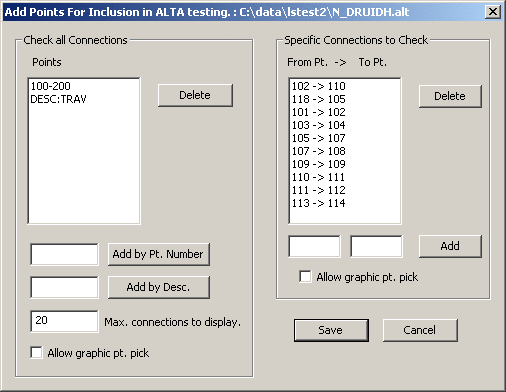
The above dialog box allows the user
to define the points to be included in the ALTA report processing.
There are two sections in the .RPT file created through the ALTA
reporting. The following report shows the sections of the ALTA
report generated by the data in the dialog box.
The first section of the report
displays the relative error ellipses between points in the Specific
Connection list. All the connections will be displayed whether they
pass or fail the ALTA certification. The point sequences used in
this section come from the list on the right hand side of the above
dialog box.
The second section of the report
performs an ALTA tolerance test on the points in the "Check all
Connections" list. Every possible connection between the points
listed will be checked. In this section, only the worst connections
will be shown. The number of connections shown is determined by the
"Max. connections to display" value in the above dialog box. The
point sequences used in this section come from the list on the left
hand side of the above dialog box.
An asterisk will be placed beside each connection shown in the report that does not pass based on the confidence interval, tolerance and PPM settings in the Adjustment section of the project settings.
Notice that you can enter points
based on descriptions in the left hand list box. If you wished to
check connections between all points with TP, EIP, MON
descriptions, enter the descriptions in the edit field and press
the 'Add' button. If TP, EIP, and MON represented traverse points,
existing iron pipes and monuments then ALTA testing would be
performed on those point types.
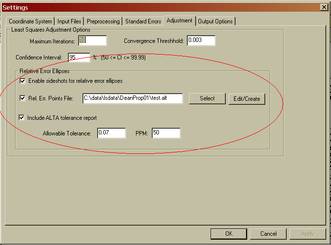
After you have created the .ALT point file you need to set a few project settings. These settings define the ALTA tolerances, specify the .ALT file to be used, and define the type of reporting to be generated. The 'Adjustment' tab sheet within the project 'Settings', has a "Relative Error Ellipses / ALTA Report" section where the ALTA report settings are located.
All the ALTA reporting settings
reside within the Relative Error Ellipse / ALTA Report box.
The 'Rel. Err. Points File:' check box must be checked, and an .ALT file must be chosen to get an ALTA report. The .ALT file defines which points will be included in the ALTA reporting. See the previous discussion on the creation of the .ALT file if you are unsure of how to create an .ALT file.
Next make sure the appropriate tolerance and PPM has been defined. The ALTA standards define their positional standard as .07 plus 50 PPM. Additionally, the ALTA standards require that the computations be performed to a 95% confidence. The confidence interval is set in the 'Confidence Interval:' edit field.
The following is a sample ALTA
report:
Relative Error and ALTA Tolerances

==================================


SPECIFIC CONNECTIONS: Tolerance of 0.070 +  50 PPM. at the 95% CI.

                                        Actual       Allowable   Ratio

 Sta.       Sta.           Dist.        Semi Major   Semi Major  Actual/Allowable  Semi Minor  Max. Err. Az.

 27         500          204.5030      0.0793       0.0802      0.9890            0.0588       S 85-06'32.2"E

 500        502           66.8572      0.1132       0.0733      1.5432            0.0842       S 86-05'06.7"E *

 34         36           237.9748      0.0731       0.0819      0.8920            0.0731       N 00-00'00.0"E


ALL CONNECTIONS: Tolerance of 0.070 +  50 PPM. at the 95% CI.


All possible connections between the following points were checked:

505,506,507,508,509,510,511,512,513,514,515,516,517,518,519,520,521,522,523,524,525,550,551,552,553,554,555,556,

557,558,559,560

1225 connections tested, the 10 largest relative error ellipses will be shown:


                                        Actual       Allowable   Ratio

 Sta.       Sta.           Dist.        Semi Major   Semi Major  Actual/Allowable  Semi Minor  Max. Err. Az.

 506        556          806.5402      1.0818       0.1103      9.8054            0.2586       S 86-37'40.4"E

 507        556          827.2364      1.0832       0.1114      9.7268            0.2446       S 86-37'05.9"E

 505        556          818.7994      1.0779       0.1109      9.7158            0.2386       S 86-48'24.5"E

 508        556          854.9436      1.0836       0.1127      9.6108            0.2477       S 86-38'39.4"E

 509        556          880.6338      1.0848       0.1140      9.5129            0.2489       S 86-45'39.4"E

 521        556          798.2729      1.0387       0.1099      9.4500            0.2318       S 87-22'50.2"E

 512        556          793.0518      1.0334       0.1097      9.4245            0.2127       S 87-21'38.9"E

 517        556          907.2084      1.0856       0.1154      9.4106            0.2379       S 87-07'38.4"E

 510        556          918.6572      1.0861       0.1159      9.3682            0.2525       S 86-52'46.5"E

 516        556          935.1194      1.0885       0.1168      9.3228            0.2426       S 87-22'21.7"E


*** All connection combinations passed ***
If the "Ratio Actual/Allowable" is
1.0 or less, the positional tolerance of the two points have passed
the ALTA standards.
The first part of the report labeled
"Specific Connections" will show all selected connections whether
they passed or failed. If a connection failed an asterisk will be
placed at the end of the line.
The second part of the report,
labeled "All Connections" will only show the connections that
"failed" (we chose to see the worst 25).
If all the connections pass in the
SPECIFIC CONNECTION section, you will also see this message in the
report: