 Offset Distance: Sets the
offset distance from the alignment to the points. Use a positive
value for offset right and negative for offset left.
Offset Distance: Sets the
offset distance from the alignment to the points. Use a positive
value for offset right and negative for offset left.Reference Elevation: This setting controls the point elevations. The 3D Polyline method prompts to select a 3D polyline. The offset points get the elevations from the position of the nearest perpendicular offset on the 3D polyline. The Profile method prompts to select a profile file. The stations of the profile must match the alignment stations. The Constant method sets the point elevations to a fixed elevation. The Surface Model method uses a triangulation (.tin) or grid (.grd) surface model file.
Delta Z: Adjusts the point elevations from the reference elevations.
Create Interval Points: Creates points along the alignment at the specified interval. There are separate intervals for line and curve segments.
Space Points Evenly: For each segment, this option figures how many points fit at the interval and then adjusts the interval to make that number of points evenly spaced. For example, if the interval is 10 and the segment length is 48, then 4 points fit and this option will space them at an interval of 12.
Create Vertex Points: Creates points offset from the points in the alignment.
Create Radius Points: Creates radius points for curve segments in the alignment.
Offset Side Only: Applies to radius points and only creates the radius point when it is on the same side of the alignment as the offset direction.
Max Radius: Applies to radius points to only create the radius point when the radius of the curve is less than this amount.
Create Only Radius Points on Small Curves: When the curve radius is less than the Min Radius, only the radius point is created and not the PC, PT or mid points.
Create Curve Midpoints: Creates a point midway along the curve when the curve length is greater than the specified Min Curve Length.
Minimum Deflection Angle: At an alignment vertex between two line segments, when the deflection between the line in and line out is greater than this value, only a single offset point is created. Otherwise two offset pointss are created, one for the line in and one for the line out. Set this value to 0 to always have only a single offset point. Set this value to 180 to always have two offset points.
Deflection Distance Tolerance: Sets how close together two offset points should be set on vertex deflection points. When the vertex point is set to get two offset points, but the offset points are within this tolerance of each other, then only a single offset point is created instead of two.
Starting Point Number: The new point numbers will increment starting from this number.
Point Group to Assign: Creates a point group for the new points created by this command.
Create 2nd Offsets: Creates a second set of points at the 2nd Offset Distance.
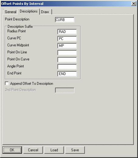 The Description settings control the
point descriptions for the various types of new points. The
Append Offset To Description option adds the offset amount
to the description of each point.
The Description settings control the
point descriptions for the various types of new points. The
Append Offset To Description option adds the offset amount
to the description of each point.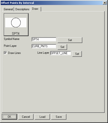 The Draw settings have the symbol and
layer for the points. The Draw Lines option is for drawing
lines between the alignment and the points.
The Draw settings have the symbol and
layer for the points. The Draw Lines option is for drawing
lines between the alignment and the points.