Footprint Creator is a command that allows for the
creation of a library and placement of building footprints. The
command is run from the Area/Layout menu and found in the Layout
Utilities sub menu. The command inserts footprint drawings and uses
the layering scheme in them to place the footprints with options.
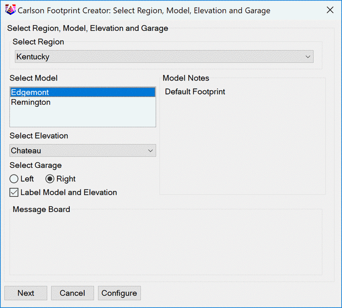
Footprint Creator allows the person producing plans to
include optional aspects of designs such as; locating the garage
left and right and including details such as driveways. Labeling
tools are provided should it be desired that elements of the
footprints are called out in the plans.
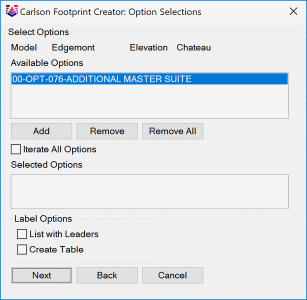
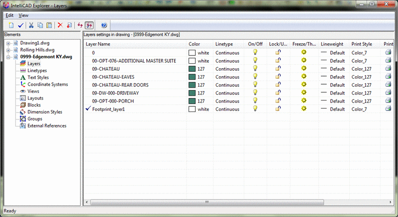
Footprint drawings may contain optional elements to be included
upon placement. In this case an option is a master suite. This is
read from the source drawings layering convention, layers
containing "-OPT" display as options. To place an option select it
by single clicking and choose the Add button. To remove it select
it from the Selected Options pane and then select the Remove
button. The Remove All button does just that and allows you to
restart the selection of options.
Additionally, Iterate All Options if toggled along with the
final creation method of Place on Building Pads will place and all
options and combinations of all options. This option only has an
effect if Place on Building pads is chosen.
The list options toggles will annotate the options either by leader, create table or both.
Use the back button should you realize a different footprint is needed.
Select the next button to select further options.
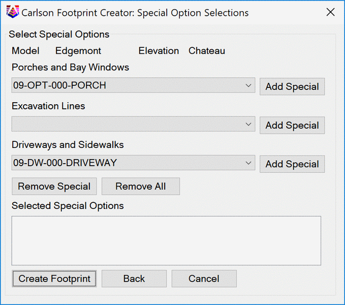
The source drawing's layering scheme is used to allow for the placement of porches and bay windows. The command reads the drawing and displays any porches or bay windows available. The layer schemes for porches and bay windows are any of the following; "##-OPT-000-COVERED LANAI", "##-OPT-000-PORCH" "##-OPT-155" or "##-OPT-156". If none are included this pull down will be blank.
Excavation Lines
Excavation lines are also read from the source drawing. The layer scheme for excavation lines is "##-EXC". If none are included this pull down will be blank.
Driveways and Sidewalks
The source drawing can also include driveways. The layer scheme for driveways is "##-DW" and for sidewalks is "##-SW". Again, if none are present in the drawing this pull down will be blank.
Add Special, Remove Special, Remove All
The Add Special, Remove Special and Remove All buttons will add the option selected for the corresponding list. Remove them individually or remove them all.
Create Footprint
When ready to place the footprint select Create Footprint. You will be prompted to select the method for creation.
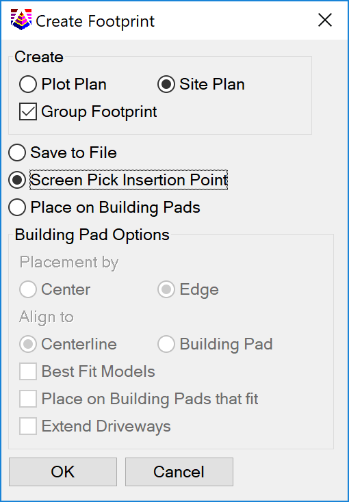
Create
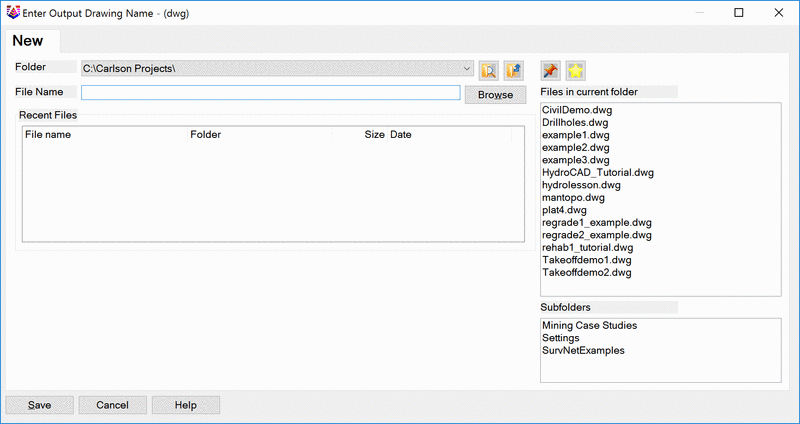
Save to File
Enter Output Drawing Name
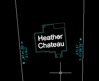
Screen Pick Insertion Point
Pick an insertion point and the rotation for the footprint. The
command will continue to prompt for insertion points until canceled
allowing for multiple placements of the same model, elevation and
options within the same command execution.
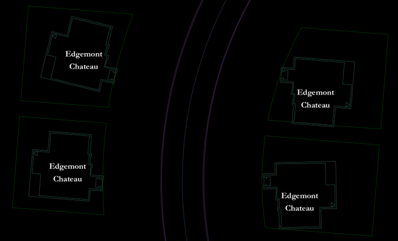
Place on Building Pads
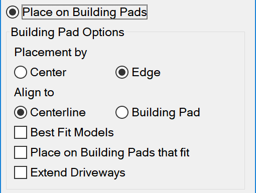
Footprints will be placed in each building pad selected and rotated toward the selected alignment option. The footprints will be placed by edge (driveway side) or centered on the building pad. When the alignment is by centerline, the footprint will be placed perpendicular to the centerline. When alignment is by building pad it will rotated the footprint along the edge of the building pad.
|
|
|
||||
|
|
If no option is selected, all Models and Elevations selected on
the initial Select Region, Model, Elevation and Garage page will be
placed within every Building Pad.
This option will adjust the footprint forward and back as well
as side to side until the footprint fits within the building pad.
If multiple models are selected on the initial Select Region,
Model, Elevation and Garage page this will attempt to fit he
highest priority model/elevation on each Building Pad. Once a
footprint has placed on a building pad the building pad will no
longer be processed. This is used to place the highest priority
models in the selected building pads.
Like the Best Fit Models, this only places footprints that fit
within each building pads. This option will continue to process
building pads that footprint have been placed in resulting with
multiple footprints within any building pad that the footprint fits
within.
This option will prompt for Edge of Pavements for Driveway
Extensions. Multiple targets may be selected and the tool will use
these targets while extending closed polylines representing the
driveway. The layer scheme for the driveway extension must contain
"DRIVEWAY". This is different than the Special Optional Selections
of driveways and sidewalks these will be on footprint layers
"##-Elevation-Driveway" and placed without using the optional
selection.
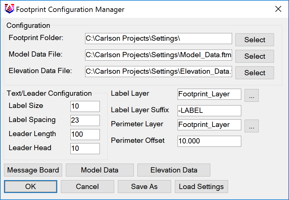
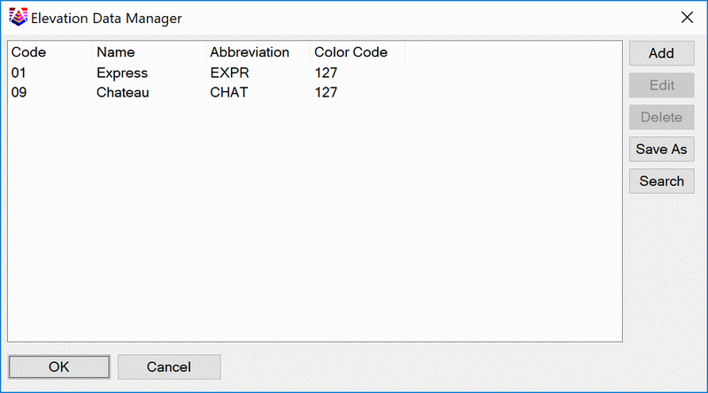
To configure Footprint Creator select the Configure
button on the first dialog. This must be coordinated with the
drawings and directory structure for them in order for the command
to work properly.
Footprint Configuration Manager