Fit Structure
The purpose of the Fit Structure feature is to place a structure
(or the footprint) within a bounding polygon. For example, a
house foundation - the footprint - within the limits of the setback
lines of a lot – the bounding polygon.
The user can easily insert a structure footprint within a lot or
bounding polygon near its final location. The footprint then
it can then be conveniently rotated and/or translated, in user
definable increments, to the exact position desired.
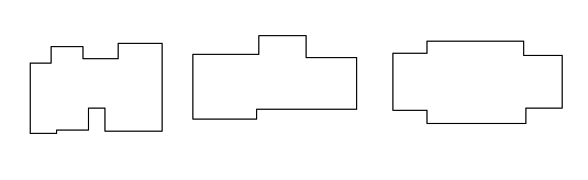
Footprint Templates
The template, a full scale definition of a structure’s footprint,
must be defined prior to placing it within the bounding
polygon.
Templates are not AutoCAD drawings but they can be imported from
AutoCAD drawings.
The data specifying the dimensions of a template is stored in a
binary format and cannot be manipulated without using the Template
Manager. Once a template is placed in the drawing, it becomes a
C&G footprint polyline. Since it is a C&G polyline, it can
be queried and manipulated using ordinary AutoCAD and CGSurvey
commands.
Template Manager
The Template Manager is used to manage the templates for the
various projects you work on. For example, the various house
footprints used in a given subdivision can be defined as templates.
The templates can then be placed in a lot in an “as” or “reverse”
orientation and reused as many times as necessary. You can use the
Template Manager to define templates directly or import the
templates from existing AutoCAD drawings.
The Template Manager allows you to organize your templates within
projects. You can name the projects in a meaningful way then
import the templates into the project “folder”.
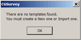
The Fit Structure Command
When you choose the Fit Structure feature from the Cogo menu for
the first time, a dialog warns you that you have no templates
defined then brings up the Template Manager.
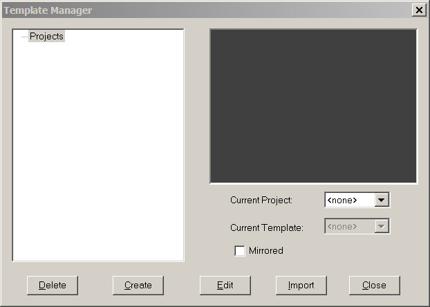
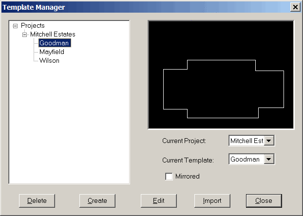
In the dialog below you will notice that there is nothing listed
under the Projects item. This means that you will have to
either create a template or import one from an existing
drawing.
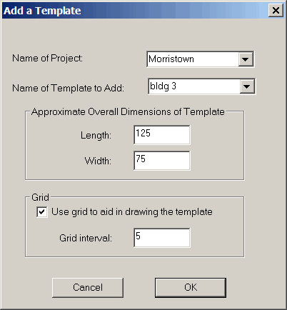
Creating a Template:
To create a new template, click the Create button. This brings up a
dialog that allows you to configure the simple drawing in which you
will create a template. This dialog allows you to specify the
name of the project, the name of the template and asks about the
approximate overall size of the template. If the structure
template is made up of right angle segments you may want to specify
a snap grid to aid you in laying out the template. You should be
aware that the create template method
should only be used for very simple templates and that it does not
allow you to edit the structure once it is added to the Template
Manager.
When you are done configuring the create template drawing
interface, click OK and you will be see an empty AutoCAD screen
upon which you can draw the template. The template is merely a
closed polyline. The C&G Polyline by Points interface is used
but in this case there will only be normal AutoCAD points picked
(also known as graphic points designated as GR-PT). The polyline
must be closed - so use the C for Close command line option for the
last line segment in the template. Once you enter the Close option
keyword for the polyline you are working on, the drawing window
closes and the template is imported into the Template manager as
shown below.
Note: You must click on the
template name in order to see its shape in the window on the right
and to choose it as the current template.
Importing a Template
The Create template method is only useful for very simple
templates. For more complicated templates and projects with
multiple structures, it is recommended that you use the Import
method. To import a template you must create a separate drawing,
then draw all of your templates at full scale on the layer
specified for templates (see Fit
Structure Setup).
Create a separate template drawing
Begin the importing of a template by creating a new drawing file as
a repository for all the structure template drawings used in a
specific project. For this example we will create a new drawing
named Mitchell Estates bldgs.dwg. This file will only contain the
structure template drawings for this project.
Select the CAD File menu
then select the menu New
item
You may be asked to choose a drawing template (not to be confused
with the structural template polylines you are about to
create). It is generally easiest to use the default acad.dwt
drawing template but you may also specify one of your own
choosing.
In this new drawing create a layer having the name specified in
Fit Structure Settings and
make this layer current. You can accomplish this by using the CAD
Layer Manager. To open the Layer Manager, from the Format menu
choose the Layer menu item.
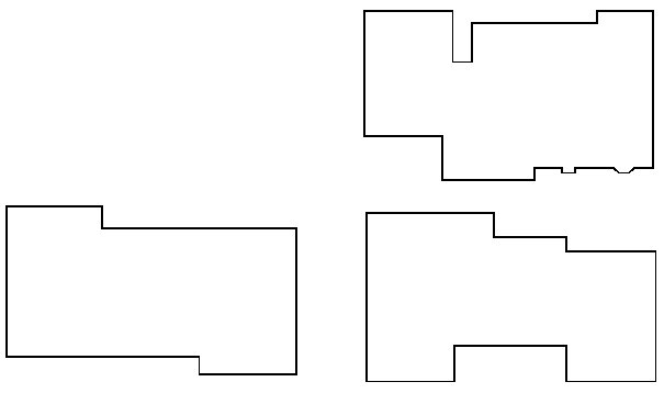
In the new drawing, draw the templates (house footprints for
example) you will be using in your project. A structure
template must be a closed polyline and may contain arc
segments.
Draw the individual house footprints. It is recommended that
you use either the C&G Polyline by Points feature or use the
standard CAD PLINE command - on the Draw menu choose 2D
Polyline.
You could also use the C&G Quick Traverse feature to traverse
around the building However, if you use Quick Traverse to create the footprint
you must then convert the C&G lines created by Quick Traverse
to polyline. To do this you can use a utility on the CGTools
menu, Join Nearest.
Once you have created the templates needed, close and save the
template drawing file. You can come back to this drawing at
anytime and add or modify templates as needed.
Note: If you change a
template in the original template drawing, you must be re-imported
using the Template Manager. First, use the Template Manager’s
Delete feature to delete
the old template, then re-import the changed template from your
template drawing file.
Placing a Footprint:
Return to the original drawing into which you wish to insert the
footprint. In this example Mitchell Estates.dwg will be used
to place structure footprints within lot setbacks.
Select the Fit Structure
menu item.
If this is the first time you have run the command and no templates
have been specified, you will be informed of this by a warning
dialog. Click OK
in the warning dialog and the Template Manager will come up.
If you have inserted a template prior to running this command, the
following prompt will be seen at the command line:
Choose a structure
template
[Set template/Current-template
(Wilson)/Mirror-current/Done] <C> :
Select “S” for Set template
to bring up the Template
Manager.
The Template Manager
As mentioned earlier, the Template
Manager is used to manage the structure templates you use
for your various projects. In the left hand pane the projects
and their associated templates are arranged similar to the
directories in the Windows Explorer. On the right pane is a
drawing showing an unscaled representation of the shape of
the currently highlighted template. The highlighted template
becomes the current template when you Close the Template
Manager. The following describes the Template Manager
functions in more detail.
Delete button: This allows
you to delete a Project or an individual template.
Create button: This
allows you to generate a template "on-the-fly" while in the current
drawing file. This method of creating templates should only
be used for the simplest of templates. In most cases it is
recommended that you import pre-drawn templates from other existing
drawings.
When the Create button is
selected, the Add A
Template dialog appears (shown earlier).
Name of Project: enter a new name or
press the down arrow to select from existing projects.
Name of Template to Add:
enter a new name or press the down arrow to select from existing
projects.
Approximate Overall Dimensions of
Template:
enter an approximate length and
width. Make sure this overall dimension will include the
entire template so you will be given enough room to draw the
template - too large is better than too small.
Grid:
If you wish to have a snap grid as
a drawing aid when you create a template, check the Use grid to aid in drawing the template
checkbox and set the grid interval. You need not use a grid
but it is useful in creating simple rectangular templates.
Click OK to begin creating the
template. To create the template, pick the desired locations
for the various building corners. Be sure to close the
structure perimeter by typing C and Enter. After closing the
template polyline you will be returned to the Template Manager.
Import button:
clicking this button allows you to
import the template from another drawing file. As described
earlier, you should create a separate template drawing. In
that drawing draw the required templates as closed polylines.
The templates may contain arcs.
When you select the Import button a
dialog (shown earlier) comes up asking you to enter or select a
Project Name and to specify
the Name of Template to
Add.
The Project Name can be
anything you wish but is often the name of the subdivision or the
client name. The template name can also be anything you
wish. It should generally reflect the type or style of
structure the template represents.
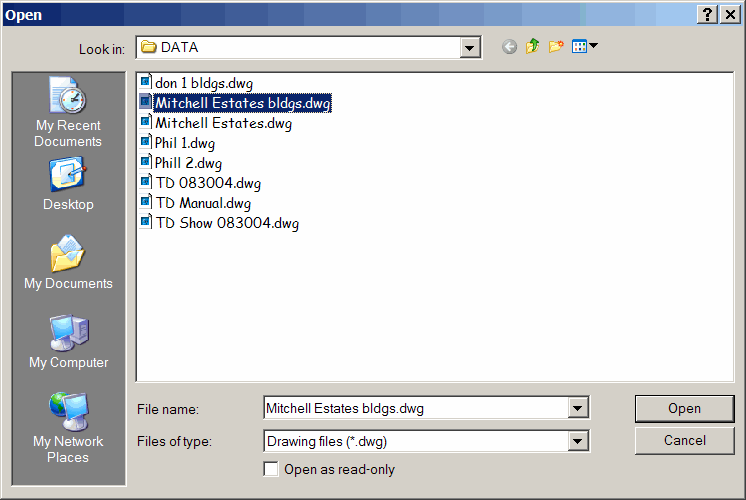
After filling out the project and template names and clicking
OK, a file dialog will be
displayed. Choose the drawing file you created earlier
containing the template(s) you wish to import.
After closing the file dialog the template drawing will be shown
and you will be asked to choose the template polyline. When
you pick the template polyline its geometry is stored in a special
file reserved for template information and you will be returned to
the Template
Manager.
If you highlight the newly imported template on the left hand pane
it becomes the current template and you should see it displayed in
the right hand pane.
If you wish to import another template just repeat these steps as
many times as necessary.
By highlighting the template name it is made the current
template. You may choose to mirror the current template on
the Y axis by checking the Mirrored checkbox. All you need do
now is click the Close
button to close the Template
Manager and place the footprint in the drawing.
Fit Structure Example
The following file names will be used when describing the following
example:
Coordinate File:
Mitchell
Estates.crd
Drawing File:
Mitchell
Estates.dwg
Template Drawing File: Mitchell Estates
bldg.dwg
Note: The template drawing
file may have several templates in the same drawing file. For
example you may have a subdivision with many different house
footprints.
Import the templates
Open the subdivision drawing file, in this case; Mitchell
Estates.dwg, and the associated coordinate file: Mitchell
Estates.crd.
The subdivision drawing should already exist and you should have
already defined the bounding polygons within which the structures
are to be placed. These bounding polygons can be defined
either by polylines (arcs are allowed) or lines and arcs. The
lots and setbacks (bounding polygons) can also be defined using a
C&G Point Group or Groups.
Once the subdivision drawing is open and has been prepared for the
placement of structures choose Fit
Structure from the menu.
If you have not run the Fit
Structure command and set a current template in this drawing
session, the Template
Manager dialog will appear.
The first task will be to create a project and import templates
from the template drawing file, Mitchell Estates bldg.dwg.
Select the Import button and fill in the project name and template
name.
In this example the subdivision name is Mitchell Estates and the
house model being added to the template list is the Wilson.
Next a drawing file dialog will be displayed. Highlight the
template drawing file (in this case Mitchell Estates bldg.dwg) and
click the Open button and
use the cursor to choose the polyline representing the template to
be imported.
After choosing the template polyline, you will be returned to the
Template Manager. You
will notice that the template you just chose has been added to the
template manager under the project you selected. To see
its shape and make it the current template, click the template name
under the current project.
You may continue to add templates as required. Click
Close to begin placing the
template in the subdivision drawing.
After the Template Manager closes you will return to the main
drawing and see the following prompt:
Pick the lot within which the
structure will be placed [cg-Point-group/Done]
<pick>:
Pick a polygon or a series of lines
that define a closed lot boundary or setback within which you wish
to place the structure. Type P and Enter to use a C&G
point group file to define the bounding polygon.
Place the structure in the bounding polygon
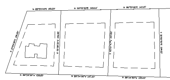
Once you have specified the bounding polygon you will be asked to
place the structure near its final location in the bounding
polygon. Move the structure near its desired location using
the mouse and click the left mouse button to place it at that
location. Once you have picked the approximate location for
the structure you will then be allowed to rotate and move the
structure to its exact final location.
Note: If you need to adjust
a template further once it has been placed within the bounding
polygon and you have exited the Fit Structure command, you can run
the Fit Structure command again and pick the existing structure
instead of using a template.
Adjust the structure
After placing the structure in the bounding polygon you will see
the following prompt at the command line:
Adjust structure
[Move/Step-move/step-Rotate/roTate/rot-Ninety/Parallel/On-boundary/setUp/Done]
<D>:
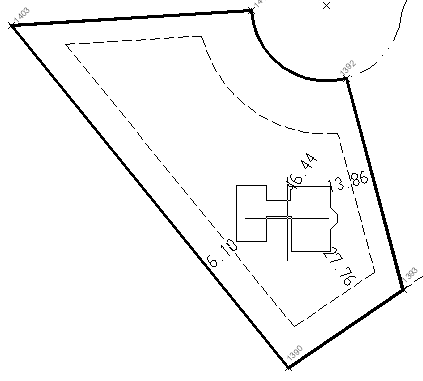
You are now at the stage were the structure can be adjusted to its
final desired location with relationship to the setback lines and
its orientation with respect to the street and other features.
In all the commands used to adjust the structure, the distances to
the bounding polygon may be displayed at the appropriate corners of
the template (see example below). You may turn this distance
display on or off or view or change other fit structure parameters
using the setUp option (type U and Enter at various the
prompts).
Move:
Type M and Enter to "drag" the
structure around using the mouse cursor - similar to when you first
placed the structure in the bounding polygon. This option is
only meant for moving the structure in a gross, imprecise way and
thus allow you to place it near its final location. After
using this option the structure can be more finely adjusted using
one of the other options described here.
Step-move:
To move the structure up, down,
left or right, using the arrow keys on the keyboard, type S and
Enter. The following prompt will appear:
Press arrow keys to move 1.000 dwg units
[setUp/Done] <D>:
Now you can use the arrow keys on your keyboard to move the
structure by steps in the X and Y directions. The distance moved
per keystroke is indicated at the command line - in this case the
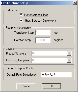
structure moves 1 unit each time you press an arrow key. To
change the per step increment, type U for setUp. This brings
up the Fit Structure Setup
dialog, allowing you to change the Translation Step setting (see
below).
Click OK to return to the Adjust Structure command
line.
Step-Rotate:
If you type R and Enter for
step-Rotate you can then
use the up and down arrow keys on the keyboard to rotate the
structure by small rotational steps.
The following prompt will appear:
Use down/up arrow keys to rotate 10°00'00"
clockwise/ccw [setUp/Done] <D>:
Rotate:
To rotate the structure, type R and
Enter. The following prompt will appear:
Rotate structure to desired orientation:
[setUp] <pick>:
Use this option to rotate the
structure by moving the mouse. Left clicking will place the
structure at the current rotated orientation. This method of
rotation is not precise and is thus useful only for gross
rotational movements.
rot-Ninety: Type N and Enter to rotate the structure
90 degrees in a clockwise direction.
Parallel:
Type P and Enter to rotate the
structure so that one of its sides is parallel to a specified line
segment on the bounding polygon.
First, select the side of the
bounding polygon that you wish to be parallel to a selected side of
the structure.
Next, select the side of the structure that is to be parallel to
the previously selected line on the bounding polygon.
After picking the side on the structure the structure will be
rotated into position.
Note: If the rotating the
structure about its geometric center to make the selected sides
parallel to one another will cause an encroachment, an error
message will be displayed, no changes will be made, and you will
return to the Adjust
Structure ... prompt.
On-boundary:
Type O and Enter to choose a point
on the structure that is to touch a selected point on the bounding
polygon. This is accomplished by translation only.
Pick the point on the bounding polygon where
you want the structure to touch: Pick the point where the
structure touches the bounding polygon.
Choose the point on the structure that you
want to touch the bounding polygon: Pick the point on the
structure that touches the bounding polygon.
If choosing a structure corner as
the point to touch the bounding polygon, you should use the end
point snap. If you do not use end point snap, the translation
of the point picked to the bounding polygon will likely cause the
corner of the structure to encroach. You can specify end
point snap when picking the point on the structure by typing in
"end" and Enter at the prompt, then you merely need to pick a point
on the structure near the desired corner to actually specify the
corner point.
Note: If the translating the structure
to make the selected point touch the bounding polygon at the
selected point would cause an encroachment, an error message
will be displayed, no changes will be made, and you will return to
the Adjust Structure ...
prompt.
Completing the adjustment process
Once you are satisfied with the location of the structure type D
and Enter and you will see the following prompt:
Creating structure coordinate
points:
Enter description for structure
corner points <footprint_pt>:
You can accept the default description shown in brackets by
pressing Enter or you may type in a description that will help you
identify this particular structure and lot.
The corner and any radius points for the current location of the
structure are stored in the current coordinate file and, if
Auto plot points is ON, the
points are drawn.
After storing the points for the previously placed structure you
will see the following prompt:
Choose a structure template [Set
template/Current Template/Mirror current/Done] <C>:
Press Enter or C and Enter if you wish to repeat the
process and place the current structure template in the same or
another bounding polygon.
If you wish to place a mirrored (“reverse”) version of the current
structure template in a bounding polygon, type M and Enter.
If you wish to place a different structure in a bounding polygon,
type S and Enter to bring up the Template Manager, allowing you to
pick a new template.
If you are done placing templates for now, type D and Enter for
Done.
Adjusting an existing structure
At any time you may adjust an existing structure by choosing
Fit Structure. If there are
existing structures in the drawing, it will be detected and the
following the prompt will appear at the command line:
Pick existing structure to adjust
or choose a structure template.
[Set-template/Current-template(Wilson)/Mirror-current/Done]
<C>:
At this prompt you can use the mouse to pick an existing
structure to adjust. You can now use any of the
adjustment methods described above to further refine the location
of the structure. After the adjustment process is complete
the coordinate file is updated to reflect the adjusted locations of
the structure's corner and radius points.
Note: When you pick an
existing structure, any plotted corner point symbols are
temporarily removed to facilitate the adjustment process.
Once you are done adjusting the existing structure, these points
are re-plotted at their new adjusted locations
At this prompt you may also choose to place a new structure in a
bounding polygon. To use a different template, type S and
Enter to bring up the Template
Manager and allow to choose the desired template. If
you have already placed a template in the current drawing session,
the prompt will indicate the current template. By typing C
and Enter or just pressing Enter you can choose to place the
current template in a bounding polygon or you can type M and Enter
to place a mirrored version of the current template:
Prompts
Template Manager dialog:
create or choose a template to place within a bounding polygon (a
lot)
Add a Template dialog: Used
in conjunction with the Template Manager dialog to add a template
to a given project.
if you have already specified a template to use but no templates
have been placed in the drawing:
Choose a structure
template
[Set template/Current template
(Wilson)/Mirror-current/Done] <C> : Type "S" and Enter
to bring up the Template Manager dialog. Type "C" and Enter
or just Enter to use the current template. Type "M" and Enter to
mirror the current template. Type "D" and Enter when done
placing templates.
if a structure/template exists in the drawing or you have already
specified a template to use:
Pick existing structure to adjust
or choose a structure template.
[Set-Template/Done]
<S>: To adjust an existing structure pick it on the
screen. Type "S" and Enter or just Enter to bring up the Template
Manager dialog to choose a new template. Type "D" and Enter
when done.
after you set a new template or chose to use the current one:
Pick the lot within which the
structure will be placed [c&g-Point-group/Done]
<pick>: pick the polyline or a series of lines that
define a closed polygon within which the structure template will be
placed. Type P and Enter to specify the bounding polygon
using a C&G Point Group file.
Place the structure near its final
location in the bounding polygon <pick>: Drag the
structure template to the desired location and click the left mouse
button to place the structure.
after you place a template or pick one to adjust:
Adjust structure
[Move/Step-move/step-Rotate/roTate/rot-Ninety/Parallel/On-boundary/setUp/Done]
<D>: Type "M" and enter to move the structure.
Type "S" and Enter to use the arrow keys to move the structure in
predefined steps. Type "T" and Enter to use the cursor to rotate
the structure. Type "R" and Enter to rotate the structure template
a predefined number of degrees using the up and down arrow keys.
Type "N" and Enter to rotate the structure 90 degrees
clockwise. Type "P" and Enter to translate and rotate the
structure template parallel to a side of the bounding polygon. Type
"O" and Enter to move the structure template so a chosen point on
the structure touches a chosen point on the bounding polygon.
Type "U" and enter to use the Setup dialog to change the step
sizes, layer names and other configuration items for the fit
structure command.
when saving the structure coordinate points:
Enter description for structure
corner points <footprint_pt>: Specify a description
for the structure template corner points to be saved in the
coordinate file or just press Enter to use the default
description.
Pulldown Menu Location: Area/Layout
> Layout Utilities
Keyboard Command:
cg_fit_structure
Prerequisite: coordinate file, pre-drawn
bounding polygon (lines and arcs or a polyline)