Range Diagram
The Range Diagram command is an interactive tool for analyzing
dragline cut scenarios. This is a quick and easy way to find
parameters such as pit width, or to size a dragline to fit the
geology. Methods of mining include Side Cast, Extended Bench, Dozer
Bench, and Spoil Bench. Output includes both drawing the sections
in CAD and printing out reports as PDF files, where each step is a
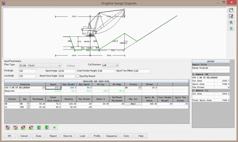
separate page. The main dialog is shown below.
Graphics Window
The visual display of the range diagram is shown at the top of
the dialog in the graphics window. Four icons are located to the
right of the window, which control display settings and camera
movement. These icons, listed from top to bottom are:
Pan: This icon will allow you to pan around the graphics
window by clicking-and-dragging the left mouse button.
Zoom: This icon will allow you to zoom in and out in the
graphics window by clicking-and-dragging the left mouse button.
Zoom Extents: This icon will zoom to the extents of the
diagram.
Set Colors and Settings: This icon will open the below
dialog, which controls the labels shown in the graphics window. To
change the colors of the various entities, use the Color Panel
which controls the color of various labels. The Select
button next to each entity will open the CAD color palette.
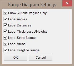
Show Current Dragline Only: This option
will only show the current dragline, rather than showing all
dragline passes at once.
Label ___: The remaining options on this dialog will label
the respective items in the graphics window.
PDF X/Y: These settings control the position where the image
will appear in the PDF withe the Report option is
used.
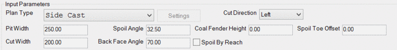
Input Parameters
This section of the help document discusses the Input
Parameters, shown below.
Many of these options are visually explained below.
Plan Type: This option
sets the mining method. Four options are available:
The
Side Cast method places the dragline on the waste material
with a previously cut pit on one side. The dragline strips the
waste material and places it into the open pit.
The Extended Bench method is similar to the Side Cast
method, but the dragline will first place waste material at the
edge of the existing highwall, thus extending the current bench
further into the open pit. This allows the dragline to position
itself on the extended bench, where it can then resume side casting
material further into the open pit. This allows the dragline to
spoil the material further into the open pit, but requires rehandle
of the material used to create the extended bench.
The Dozer Bench method is similar to the Side Cast method,
but is preceded by a dozer pushing a portion of the existing bench
into the open pit. This allows draglines with a shallower digging
reach to effectively dig out greater depths of
overburden.
The Spoil Bench method is similar to the Side Cast method,
but the dragline is positioned on the spoiled material rather than
on the active bench.
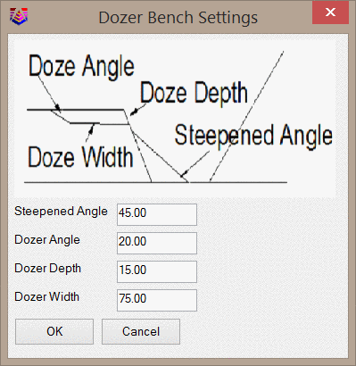
Settings: This button controls settings specific to the
Extended Bench, Dozer Bench, and Spoil Bench Plan Types, depending
on which Plan Type is currently selected. Each setting is visually
represented in the settings dialog.
The Extended Bench Settings are shown below.
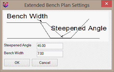
Steepened Angle: This value controls the angle,
in degrees, of the new slope of the extended bench.
Bench Width: This value controls the width of the extended
bench.
Steepened Angle: This value controls the angle,
in degrees, of the spoil pushed by the dozer into the pit.
Dozer Angle: This value controls the push angle of the dozer
until it reaches the Dozer Depth.
Dozer Depth: This value controls the digging depth of the
dozer.
Dozer Width: This value controls the width from the existing
highwall to the start of the flat portion of the dozer bench. Note
that the full dozer bench may be longer than this value depending
on pit geometry.
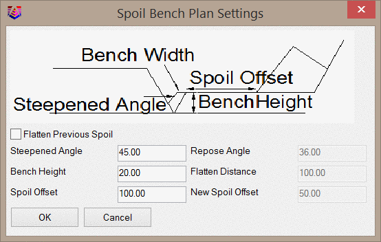
The Spoil Bench Settings are shown below.
Flatten Previous Spoil: This option is only
applied when two dragline passes are designed. When selected, the
left three settings of this dialog will be made unavailable and the
right three setting will become available. When a previous spoil
pile is flattened for the dragline bench, it is always pushed
further into the pit, away from the unmined ore.
Steepened Angle: This value controls the spoil angle from
the pit floor up to the dragline spoil bench.
Bench Height: This value controls the height of the dragline
spoil bench.
Spoil Offset: This value controls the width of the dragline
spoil bench.
Repose Angle: When flattening a previous spoil pile for the
new dragline bench, this value controls the repose angle, in
degrees, of the pushed material.
Flatten Distance: When flattening a previous spoil pile for
the new dragline bench, this value controls the width of the spoil
that is flattened in preparation for the dragline.
New Spoil Offset: When flattening a previous spoil pile for
the new dragline bench, this value controls the spoil offset from
the previous spoil pile.
Cut Direction: This options
determines whether the cut is advancing to the right or the left in
the graphics window.
Pit Width: This value
sets the width of the existing, open pit. This can represent a
previous pass, or a boxcut.
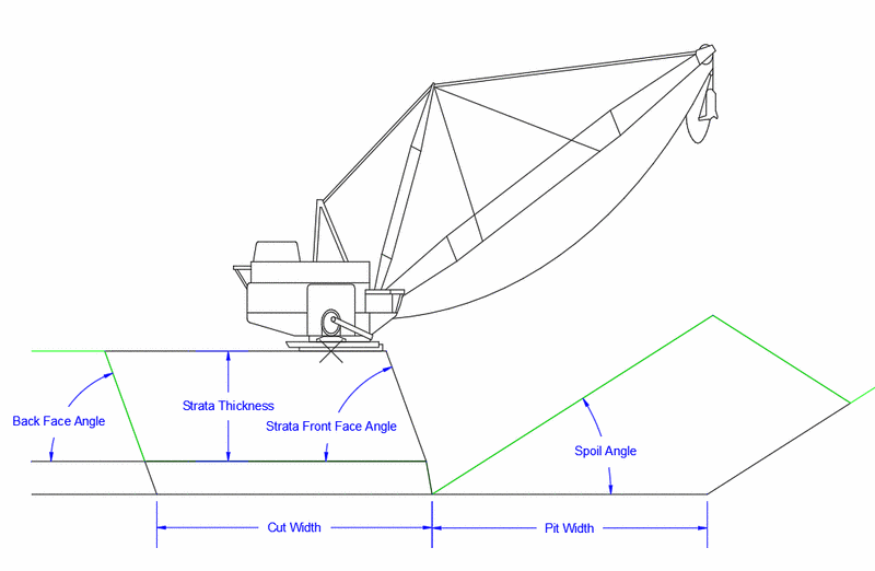
Spoil Angle: This value
sets the angle of repose, in degrees, for the spoiled
material.
Coal Fender Height: This value sets the height of the
remaining coal that may be covered with spoil. This wedge of coal
that is covered by the spoil is known as a fender.
Spoil Toe Offset: This value places the toe of the spoil
the specified distance from the bottom of the coal seam.
Cut Width: This value
sets the width of the new cut. This is the field that is frequently
changed in order to find an adequate pit size.
Back Face Angle: This
value sets the highwall angle, in degrees, for the new cut
for all strata.
Spoil by Reach: This option places the top of the pile at
a distance specified in the Spoil by Reach column of the
Dragline and Seam Data section of the dialog. When selected, the
Coal Fender Height and Spoil Toe Offset fields will be
unavailable.
Dragline and Seam Data
This section of the help document discusses the Dragline and
Seam Data inputs, shown below.
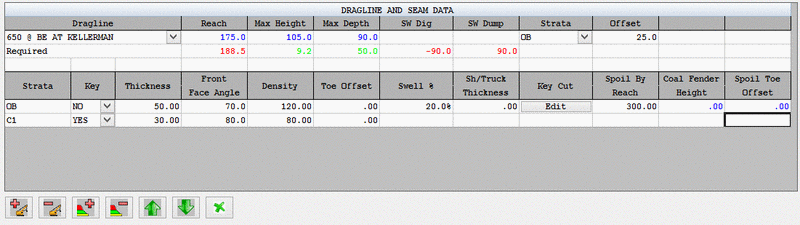
Note that this section of the dialog uses colored
text to highlight design flaws. Black text is used for simple input
values, blue text is used for maximum available values, green text
is used for values that are attainable with the current design, and
red text is used for values that are not attainable with the
current design.
Dragline: This
dropdown menu sets the dragline to use for the current pass. When
selected, a list of predefined draglines will be shown. Draglines
may be added/edited via the Define Dragline Equipment command
(Surface Mining Module > Surface Pulldown Menu).
Reach: This value
displays the horizontal reach of the selected
dragline.
Max Height: This value
displays the vertical dumping height of the selected dragline, as
measured from the bottom of the dragline.
Max Depth: This value
displays the vertical digging depth of the selected dragline, as
measured from the bottom of the dragline.
SW Dig: This value
displays the required dragline Swing Angle, in degrees, on the
digging side. If this value is shown in red, then the dragline
cannot reach the entire cut, even with a -90 degree swing
angle.
SW Dump: This value
displays the required dragline Swing Angle, in degrees, on the dump
side. If this value is shown in red, then the dragline cannot reach
far enough into the pit to adequately dump the waste material, even
with a 90 degree swing angle.
Strata (Top Section): This option
sets the strata on which the dragline is
positioned.
Offset: This value sets the distance
between the highwall and the center of the dragline
tub.
Strata (Bottom Section): This column lists all strata to be handled
in the current dragline pass.
Key: This column marks each strata as key or non-key (waste)
material. Only non-key material will be spoiled.
Thickness: This column controls the thickness of each
strata.
Front Face Angle: This column controls the highwall angle,
in degrees, of each strata. Note that a value of 90 represents a
vertical highwall.
Density: This column sets the density for each strata.
English units are set to lbs/ft3 and metric units are
set to kg/m3.
Toe Offset: This column controls the bench width between
strata.
Swell %: This column lists the swell percent of the spoiled
material. A material with a swell of 10% will occupy 1.1 times it's
original volume after it has been spoiled.
Sh/Truck Thickness: This column controls the thickness of
each non-key strata that is to be excavated by truck and shovel
(material that won't be spoiled into the open pit).
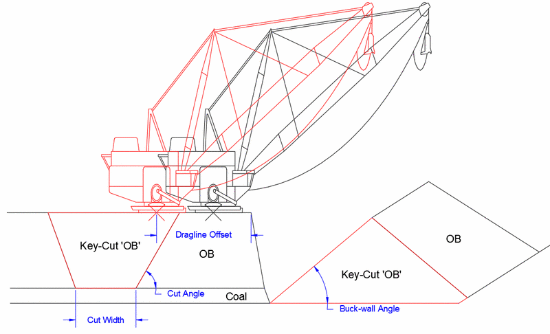
Key Cut: This column controls if each non-key material is to
be excavated with a key cut. Clicking the Edit button will
open the below dialog, which is shown next to an example of the
results it will produce.
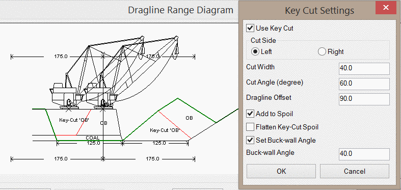
Use Key Cut: This option toggles the use of the
key cut.
Cut Side: This option controls the location of the key cut -
either the right or the left side of the cut area.
Cut Width: This value controls the width of the key cut.
Cut Angle (degree): This value controls the cut angle
of the key cut.
Dragline Offset: This value controls the distance between
the crest of the highwall and the center of the dragline, during
the key cut.
Add to Spoil: This option will actually spoil the material
excavated in the key cut. If not selected, the material from the
key cut is assumed to be haul away to another dump
location.
Flatten Key-Cut Spoil: This option is only available when
the Add to Spoil option is selected. This option will flatten the
top of the spoil pile created from the key cut. When selected, the
Spoil Bench Settings dialog will be used to set the parameters for
the flattened bench.
Set Buck-wall Angle: This option will set the angle of repose
for material spoiled from the key cut. This allows for two angles
of repose to be displayed in the overall spoil pile. Several of the
above parameters are represented below.
Coal Fender Height: This column displays the required coal
fender height for the given Spoil by Reach value. This value is
calculated automatically.
Spoil Toe Offset: This column displays the required spoil
toe offset for the given Spoil by Reach value. This value is
calculated automatically as the distance from the toe of the spoil
to the to of the strata.
Spoil by Reach: Yes or No. This column sets the spoil
distance for each strata when the Spoil by Reach toggle above is
selected.
Bottom-row Icons: At the bottom of the Dragline and Seam
Data section of the dialog are six icons, shown below.
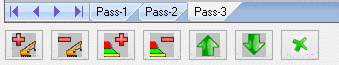
Listed in order from left to right:
Add Pass: This icon will add an additional dragline pass to the
cut. This can be a different dragline or an additional pass of the
same dragline. Each dragline pass is listed on a separate tab. Note
that any strata layers listed for one dragline pass will be
completely excavated in that pass. If a strata is to be excavated
with dragline pass #2, that strata should not be listed in dragline
pass #1. An example of the tabs shown for three dragline passes are
shown above.
Remove Pass: This icon will remove the currently selected
dragline pass.
Add Strata: This icon will add a new strata to the current
dragline pass.
Remove Strata: This icon will remove the currently selected
strata.
Move Up: This icon will move the currently selected strata
up in the list.
Move Down: This icon will move the currently selected strata
down in the list.
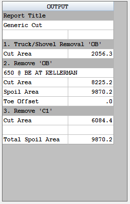
Output
The output window will output the results of each step of the
dragline sequence. Steps will be added and removed
automatically.
Additional Commands
This section of the help document discusses the additional
commands on the dialog, shown below.
Draw: This buttton will draw the dragline sequence in CAD.
No dimensions will be labeled; only strata. Each step of the
sequence will be drawn separately, with the first step shown at the
bottom.
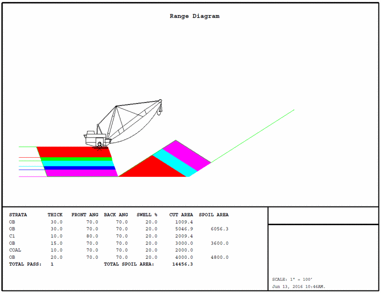
Report: This button will create a multi-page PDF document
where each step in the section will be on a separate page. The last
page of the report will show all steps, as shown below.
Profile: This button will save a profile (.pro file type) of
the final step of the dragline sequence.
Sequence: This button will save the dragline sequence (.seq
file type). This file can be used to extrude the dragline steps
across a centerline via the Process Dragline Sequence command
(Surface Mining Module > Surface Pulldown Menu).
Pulldown Menu Location: Surface
Keyboard Command: ranged
Prerequisite: dragline equipment defined