Design Fill Surface
This command creates fill pile where the sides are a series of
slopes with benches. The side slopes start from a closed polyline.
The perimeter polyline is the toe of the pile, and the slopes will
be up and in from the footprint of the pile. Different slopes can
be used for different sides of the fill. The fill is drawn as 3D
polylines and the fill volumes are reported.
Before starting this command, the perimeter should be
drawn as a closed polyline, 2D at zero elevation, or at 3D
elevations draped onto a surface. You also need a grid file for the
existing ground surface. Design Fill Surface starts with the dialog
shown below where you specify the grid file name.
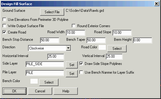
- Ground Surface: This is
the grid or triangulation surface to place the fill pile on.
- Use Elevations From Perimeter
3D Polyline: This will use the elevations on the polyline as
the toe of the fill pile to start the design.
- Write Output Grid File:
This option will create a grid file (GRD) of the fill. It includes
the original ground surface grid file, with the fill pile built
onto it.
- Round Exterior Corners: This option will create rounded corners on
the outside edges of the pile for a more realistic design. When
this is off, the corners are sharp and angular.
- Create Road: This option carves a rough road into the pile design. In
the dialog, the road Direction, Road Width and Road Slope % are specified along with a
Road Color for the road polylines to create. When
this option is active, the program will prompt for a road starting
point along the pile perimeter. The cut slopes are shifted to make
room for the road. The Bench Stop Distance is for suspending
the bench as it crosses the road to avoid combining the road and
bench widths at the crossing which tends to shift the cut slopes
too much. Within the Bench Stop Distance, the bench has a zero
width. The Bench Stop is centered at the road crossing. The
Bench Taper to the distance that the bench transitions from
full width to zero at the Bench Stop. The Berm Height adds a
berm and makes the road wider to fit the berm. The slope of the
berm matches the cut slope.
- Horizontal & Vertical Interval:
These settings control the
distance to draw the 3D breakline polylines. The horizontal
interval will run down the slope, and across the bench. The
vertical interval will run parallel with the benches. It should be
a factor of the bench height if possible, but not
required.
- Min Bench
Height: The bench is not created when the side slope depth
is less than the specified amount.
- Side Layer: This is the layer of the 3D polylines drawn
perpendicular to the benches, and running down
slope.
- Pile Layer: This layer is applied to the 3D
polyline break lines running parallel to the
benches.
- Draw Side Slope Polylines:
This option chooses whether to
draw the 3D polylines running perpendicular to the benches, and
down slope.
- Use Bench Name for Layer Suffix:
This option adds the bench name
to the Pile Layer so that each bench can have a unique name which
can be useful for having different colors for each bench for
visualization or for isolating benches by layer.
- Bench Color: This puts the bench 3D polylines in the Pile
Layer on a different, specified color so they stand out against the
slope breaklines.
- Bench Taper At Surface Tie: When a
bench meets the Ground Surface, this option tapers the bench width
to zero over this specified distance.
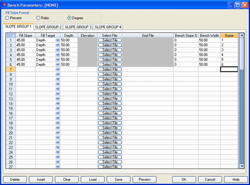 Fill Slope
Format: The slope angle can be defined in percent, ratio or
degrees. This is what is entered in the Fill Slope.
Fill Slope
Format: The slope angle can be defined in percent, ratio or
degrees. This is what is entered in the Fill Slope.
- Slope Group: Four different sets of slope schemes can be
defined. To define the another slope scheme, select other Slope
Group tab. The set of slopes are currently being edited is
indicated by the selected tab. If different sets of slopes are
defined, then the program will prompt to pick which sides to apply
each set of slopes to. All sides are assumed to be slope type one.
it is only necessary to select types two, three and/or four. If
only one slope group is defined, then it will not prompt to select
any additional sides.
- Fill Slope: The slope angle can be defined in percent,
ratio or degrees. This is what is entered in the Fill
Slope.
- Fill Target: The target to fill to for each bench can be
a flat elevation, a depth above the previous surface or bench, or
up to a grid file surface.
- Depth: The Depth must be filled in when the target
is set to depth.
- Elevation: The Elevation must be filled in when the
target is set to elevation.
- Select File: The file must be selected when the target is
set to file.
- Bench Slope %: This setting will slope the benches down for
drainage if desired. Normal setting for flat bench is
0.
- Bench Width: This is the horizontal width for the bench
in feet or meters.
- Bench Name: This is
used for pile design to name the benches for volumes. It does not
have much application in the Fill version of this command.
- Delete: This deletes one line of
data.
- Insert: This inserts a blank row to be filled
in.
- Clear: This clears the entire slope group page,
only the current group.
- Load: This loads a previously saved PIT file with
the template saved.
- Save: This saves the template as shown in the
window.
- Preview: This displays a preview of the current group
to show how the cross section of the fill will
look.
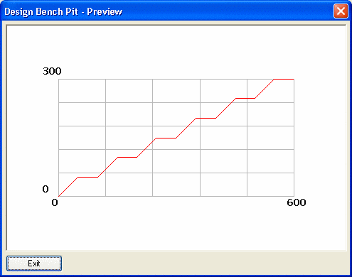

Design Fill
Surface with 2 benches
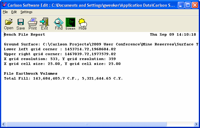
The report window appears at the end of the command to display the
volume of the fill in CY or CM.
Prompts
Design Fill Surface dialogs
Pick pile perimeter polyline: Pick the perimeter
Pulldown Menu Location: Surface in Surface Mining
Module
Keyboard Command: spoil3