This command applies a blast profile to a cut area in cross-section view. Before starting this command, the surface should be drawn as a polyline from left to right.
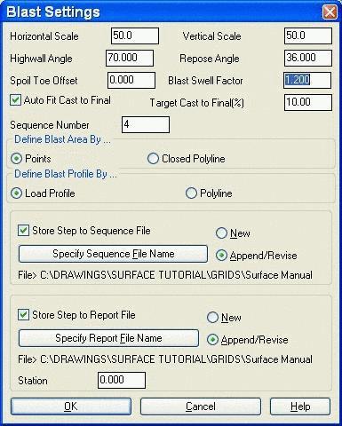
Cast Blast first brings up a dialog where you can set the scale, highwall angle and swell factor. The Horizontal Scale and Vertical Scale are used to determine the vertical exaggeration of the cross-section view. The Highwall Angle is used with the Define Blast Area By Points option as the angle from the picked points at the bottom of the blast area up to the surface. The Cut Volume Swell Factor is multiplied by the cut area to determine the fill area of the spoil pile.
The area to cut can be either a closed polyline or defined by picking the lower left and lower right points. When picking points, there is an option to select a strata polyline which will be used as the bottom cutoff for the blast area. The blast profile can be defined by either a polyline drawn from left to right on the screen or by a Carlson profile (.pro) file. Refer to the Section & Profile module for how to create a profile file.
After placing the blast profile, there is an option to adjust the blast profile points. To adjust a point, pick on the blast profile near the point to modify. This will pick up that point and you can pick a new position. When a point is moved, the program will automatically fit the updated blast profile. Once everything is set, press Enter to end the routine. The surface profile polyline is redrawn with the blast area showing the blast profile. The changed segments of the original surface are drawn in a different color.
The program reports the cut and fill end areas and the cast to
final percent which is the percent of the fill area that is in the
final spoil area. The cast to final area is defined by the area
past the line starting at the toe of cut and going up at the Repose
Angle. This starting point can be offset from the toe of cut by
using the Spoil Toe Offset field. A negative offset moves to the
left and a positive to the right. The Auto Fit Cast To Final option
will adjust the blast profile by moving the profile horizontally
such that the placed profile balances the cut and fill areas and
meets the specified Target Cast to Final percent.

There is an option to save the user input for this command to a sequence file (.seq) for the Process Dragline command and to a section report file (.cut) from the Dragline Section Report command. With the sequence file active, the program will prompt for a centerline reference point which is the point in the cross-section view that the centerline for Process Dragline passes through. If you choose a strata polyline, the program will ask for the strata name of this polyline. The Process Dragline command then prompts for a grid file that models this strata name. Besides specifying the sequence file name to write to, the sequence number is also stored. This number orders the steps in Process Dragline.
Select existing grade polyline: pick a
polyline
Pick centerline reference point on ground polyline: pick
a point on the ground polyline
Select strata polyline (Enter for none): pick a
polyline
Enter strata name for strata polyline: UB_TOP
Pick lower Left cut point: pick a point
Pick lower Right cut point: pick a point
Select blast profile polyline: pick the polyline
representing the typical profile
Cast to Final: 10.20%
Pick profile point to modify (Enter to end): pick a point on
the blast polyline
Pick new position: pick a point for the new
position
Pick profile point to modify (Enter to end): press Enter
to end
CUT: 1775.60 (sf) FILL: 2308.28 (sf)
Pulldown Menu Location: Surface
Keyboard Command: spoil
Prerequisite: Surface polyline in profile view