Surface Production Timing
This command is used for production based timing of a mineplan
to see the mine progress when defining production by time period.
It is sometimes referred to a pre-scheduler, prior to running
Surface Equipment Timing to get an estimate of mine progression.
There are 3 steps needed to prepare for Production Timing as shown
in the flow chart below. First, the mining model needs to be set up
in the Geologic Model file (PRE). This could also be the geologic
model. Next, there must be named, Carlson pit polylines
representing the mine plan. Finally, the pits lines must have
direction assigned for mining. Once these 3 items are created, the
command may be run. This command does not use highwall angles or
laybacks. It loads the mining model and vertically intersects it
with the directioned pits to obtain timing blocks.
Make Geologic Model File ----> Create Named
Carlson Pits ----> Assign Directions to Pits ----> Surface
Production Timing
The first step is to choose the Geologic Model file to process.
After it is selected, the first dialog box appears with some
initial settings. The Key Strata Recovery can be entered in the
window with Set Value, or can be set By Strata Definitions, where
it will refer to the Strata Definition File created with the Define
Strata command, or the recovery can be an attribute grid surface
found in the geologic model, with the attribute name of REC, which
may be customized. The grid would need to contain values from 0-100
for recovery. Each strata can have it's own recovery with the
second two options. The Key Strata Density is set in the same way.
Either by entering it here, or as defined in the SDF file. The
units are either pounds/cubic foot or kg/cubic meter, depending on
US units or metric units in the drawing. Finally, the Source of
Bottom Surface Model can be set here. If Strata Model is chosen,
then the routine will use all seams from the surface topography
down to the lowest strata surface in the Geologic Model file. If
Surface File is selected, then volumes will only be calculated from
the topography down to that bottom surface grid or TIN file, which
could be a flat bench elevation for example, or a complex benched
pit with many levels. A file-select window will appear next, to
choose the grid or TIN if that option is used.

Next, after selecting the pits and the mining project file, the
Surface Production Timing window appears as follows.

The first step is to select pits and move them over to the
Assignment box on the left with the Assign button. Following is a
detailed description of each item in the dialog box.
- Do Earlier / Do Later:
These buttons move the pits up or down in the Assignment
window.
- Remove, Remove All:
These buttons will move either the selected pit, or all pits from
the Assignment window to the Unassigned Pits window
- Assign: This button
will move the highlighted pits from the Unassigned window to the
Assignment window.
- Select All: This is a
quick way to highlight all pits in the Unassigned Pits.
- Inverse sorting: If
this is checked, then the pits will appear in reverse order in the
Unassigned Pits window, otherwise they are in alphabetical and
numeric order.
- Screen Pick: Allows for
manual selection of pits in plan view with a cross-hairs. Simply
place the cursor in the pits and pick in the order to mine. Hit
enter when done. The selected pits should appear in the Assignment
window in the order they were picked.
- Report pits on one row:
This option is for report formatting. If this is checked, the
report will have one row per time period and all strata quantities
and qualities will follow on that row, each in their own column. If
this is not checked, then each strata will be in its own row in the
report, with its quality to follow. This is option is usually not
selected.
- Use property
boundaries: There must be named property boundaries on
screen for this option. Production timing will automatically detect
them and break out the production by owner and property if
desired.
- Draw timing blocks: One
of the main items of output from this command. It draws the periods
as blocks of solid fill or any hatch pattern inside the pits in
plan view. They are colored by period. As they are being drawn, the
direction and progress of the mineplan can be seen for
review.
- Draw distinct outline:
This is very similar to the timing blocks, except that they are
just closed polylines with no fill or hatch. They are in their own
color, and optionally, layer. They can be used later for further
reserve calculations, or to save the mineplan without hatch or
fill.
- Draw labels: This
option places the period name in the block or outline. It is either
the user defined label, or will just use "Period1", "Period2"
etc.
- Text autosize: If this
is selected, the text will be automatically sized to fit the size
of the block outline. Otherwise, the text might be too large for
some of the smaller blocks.
- Draw labels
length-wise: Selecting this option orients the text
lengthwise to the long axis of the block outline. Otherwise it will
be placed horizontally.
- Text Size: Enter in the
text size for labels. It will use this if Text Autosize is not
selected.
- Text Style: Enter the
AutoCAD Text Style for labels and legend.
- Draw Legend: Select
this option to draw a legend of the timing blocks showing the color
and the name of the period. It will ask to pick the legend
position.
- Legend Scale: Enter in
a legend scale size to size the legend.
- Layers by Period: This
option will create a new layer for each time period and draw the
blocks and outlines in those layers.
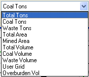
- Production Table Type:
This is a very important setting that needs to be selected for the
target material. There are 10 choices to use for production
targeting. Most common are Key Tons and Overburden Volume, but
others are available. Total Tons converts all strata to tonnages
and mines them accordingly. The NonKey density is set in a window
that appears as soon as Run is selected. Key Tons are tons of the
combined key material, which name is set in Configure /Mining.
Waste Tons will combine all NonKey strata, calculate the tons for
it and target that tonnage for production. Mined Area will target a
defined area in square feet or meters for production. Total Volume
will combine all strata, both Key and NonKey and target the total
CY or CM. Key Volume or Coal Volume will target the CY or CM of all
Key strata in the selected Geologic Model file. Waste Volume
combines all NonKey strata and targets the CY or CM of them. User
Grid will take any grid and target total quantities for production.
An example of this would be a power plant that wants to target
total BTU. The grid to select would be total BTU/area. Finally, the
Overburden Volume will take just the first NonKey strata in the
Geologic Model and target that, but still report any additional
NonKey seams below it.

- Stop at Last Period: If
this is checked, then the routine will stop after the last period
entered in the Production Table. If it is not checked, then it will
continue with the last target amount all the way through the last
selected pit polyline.
- Production Table: This
is the screen to set the production amount and time period or date.
The first column is the amount to target. This is what you have
selected under Production Table Type. The second column is the
color for that period. The next column is the hatch pattern for the
block. If it is a hatch pattern other than SOLID, then it must have
a scale factor, set in the next column. the AutoCAD Layer is set in
the next column and finally, the Label is set in the last column.
This can be anything from dates, to owners and areas. If the Labels
are left blank, then it will fill in labels such as Period3,
Period4, or month or year, etc. The Clear button will clear the
entire screen. There are Save and Load buttons for easy retrieval
of the CQT files.

- Undo: This will undo a
previous run, removing the colored blocks and outlines.
- Run: This is the button
to start the actual timing and sequencing of the pits. After the
Production Table and all the settings are good, then choose
Run.
- Finish: After the
blocks are drawn and the Surface Production Timing window comes
back, selecting the Finish button will start the calculations and
generate the quantities and qualities in the Report Formatter. Here
items are selected to appear in the report and exported to a file,
such as Excel or Access.
A finished map with the blocks drawn on it and the
corresponding report are shown here. In this example, the amount
was set to 225,000, then 250,000 tons. In the report, notice the
accuracy of the tons. Most are within a couple of hundred tons.

 Pulldown Menu Location:
Surface Mine Module - Reserves/Timing
Pulldown Menu Location:
Surface Mine Module - Reserves/Timing
Keyboard Command: calcplan
Prerequisite: Timing pit polylines