
The Pit Matrix Layout function will divide a polyline (preferably closed, but not necessary) into surface pits of any arrangement you specify utilizing temporary alignment polylines. The site and pit names are also defined in this routine. This allows for a great deal of imaginative pit configurations and layouts around difficult geometric and individual situations. The routine will insert the specified number of rows and columns of pits in a matrix form directly inside the baselines, and if used, crosslines. The mine boundary will then serve as an inclusion perimeter and create pits in the matrix form only inside of it.
Select mine boundaries:
Select TWO baselines: select objects The best pit
configurations result from baselines with equal number of
vertices.
Select TWO crosslines or hit Enter for none: select
objects Similarly with the baselines, the crosslines should
have the same number of vertices.
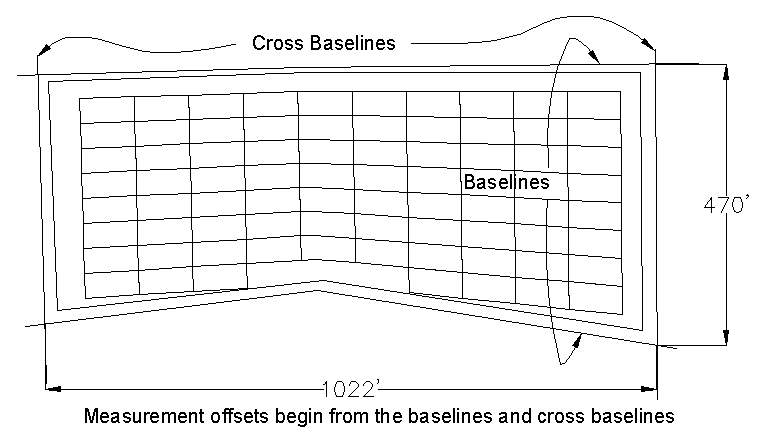
Note: Baselines are required. Crosslines are not. If just long strips of pits are desired, then just use baselines with no crosslines and enter in 1 for number of pits in the Cutting Across Baselines tab. It is also important to note that the order the base and cross lines are selected will determine where the pit naming will begin. The first baseline selected will be where Pit 1 will start, for example. The same applies to cross lines, for sub pit or block labeling. If there are no crosslines used, then the direction the baselines were drawn will affect the naming of the blocks or sub-pits.
Baselines and crosslines can and probably should be drawn
directly on top of the boundary to get exact pit sizing starting at
the boundary. They are shown off the boundary line here for
clarification of what they should look like. The matrix will begin
at the base and cross lines, wherever they are drawn.
With the initial linework completed and knowledge of the general dimensions of the layout, the user can use the following options.
Number of proportional pits: This will measure the distance between the baselines and divide the pits proportionally, evenly distributing the size of the pits as they are cut along the baselines using the Number of cuts entry. If the Min/Max options are used, Number of cuts will still be applied. For example, if only 10 pits are desired in a certain layout direction, the routine will stop at 10 pits, then a different plan may be applied from there.
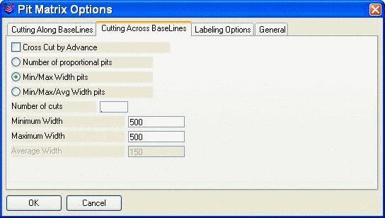
Min/Max Width pits: Enter in the minimum and maximum pit widths that will be allowed and the routine will stay within that range to fan pits around corners etc. If the min and max are the same, then all pits will be that width.
Min/Max/Avg Width Pits: This is very similar to Min/Max Width, except the average value will be the width that it will use unless it has to fan around a corner. Again, if the minimum and maximum and average are the same, say 175, then all pits will be 175 wide.
The Cross Cut by Advance option in the Cutting Across Baselines Tab should be checked if a certain pit or block size is desired, with little flexibility. Everything is grayed out if this is selected and the block sizing will begin at the cross lines.

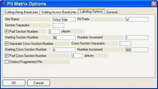
Labeling Options: Consider the pit and block scenario. A pit is defined by the base lines and broken into blocks by the cross lines. For labeling, enter a Site Name and Pit Prefix. Both base lines and cross lines can have a section separator (here a dash -). The total number of places can be set with Pad Section and Cross-Section Number so that a resulting pit number such as 056 (for 3 places) can be obtained. The starting pit (section) and block (cross-section) numbers are set in their own windows. The increment is set for both pit and block, here the pit is set to 1 and the block is set to 500. The first few pits in this example will be named: W-056-000, W-056-500, W-057-000 and so on. Distinct Fragmented pits will give a unique name to a pit that is broken due to a gap in the boundary. For example, if the long dragline pit is broken by a washout of coal, and this option is checked, then the pit will have two names: Pit 56a and Pit 56b. It automatically uses a, b, c, etc. If it isn't selected, then both will be named Pit 56.
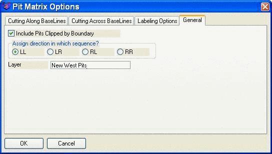
General: The option to include clipped pits (any pit that
touches the boundary) is found under the General tab. An example of
both options is shown below. The layer of the new pits is set in
the Layer box. The pits are assigned direction for timing with the
"Assign direction in which sequence?" option. If you imagine
looking down the boundary, from the first selected base line to the
second, LL will be mining from the left in each pit, to the right.
LR will be from the left in the first pit, then back from the right
in the second pit etc. RL and RR are just the opposite.


 Labeling options allow special separators.

When geometric layouts for the pits become more complicated, Pit Layout by Matrix will allow the user to design the pits to most any situation presented. It is extremely useful for "fanning" of the pit where corners or varied widths are encountered. This example above shows how a matrix of [10 X 50] can be fit inside a varied boundary such as this angular mine boundary.
Select mine boundaries: select the
boundary
Select objects: 1 found
Select TWO baselines: select the
baselines Pay attention
to which is selected first for name direction.
Select objects: 2 found
Select TWO crosslines or hit Enter for none:
Select objects:
Pulldown Menu Location: Boundary
Keyboard Command: cross_pit
Prerequisite: The routine requires a polyline boundary for
the pits to be designed inside of (better if closed), two
baselines, one on each side of the boundary, and optionally, two
crosslines to further define the extent of the "sides" of the
pits.