 Symbol
Name sets the symbol name to be plotted.
Symbol
Name sets the symbol name to be plotted.This command allows you to report and optionally label
elevations for selected surface files. You can simultaneously
analyze up to nine different surface files. Surface files can be
either triangulation (.flt or .tin) files, grid (.grd) files, or
any combination thereof. The following dialog opens when the
command is initiated:
Symbol
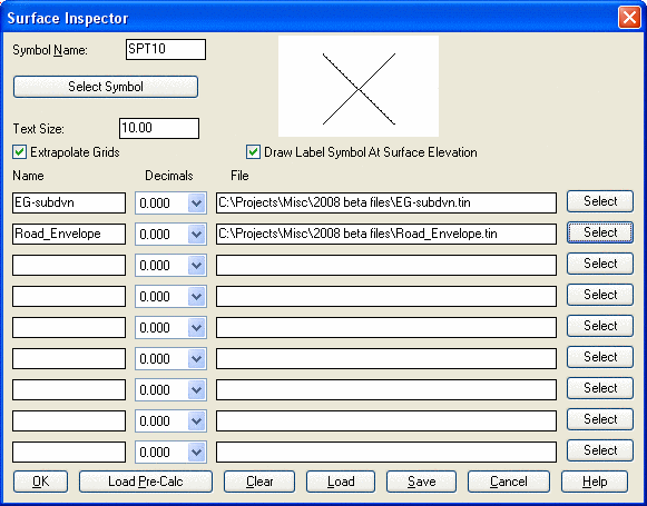
Name sets the symbol name to be plotted.Click Select Symbol to select the symbol from the symbol library.
Text Size sets the actual size (not scale factor) of the
text label placed in the drawing.
Turn the Draw Label Symbol at Surface Elevation toggle ON
if you want the symbol to be located at the actual elevation of the
surface.
Report Slope displays the slope of the surface along with
the elevation.
Report Station/Offset prompts for a centerline and
reports the station and offset in addition to the surface
elevations.
When there are two surface files, the Report Elevation
Difference option will add a third report field for the
cut/fill between these two surfaces.
Name denotes the name that will be plotted when you label
the elevation. The default value is the same as the name of the
surface file, but you can change it.
Decimals individually sets the decimal elevation precision for each selected surface.
For File, either type in the surface name to use or press the Select button to choose the surface file from a browse window.
Load Model allows you to select grid files from a list of
grids stored in a Geologic or Mining Model file. These files can be
created in the Carlson Mining module.
Clear: Clears all
values.
Load: Loads a
Surface Inspector File (.SIF).
Save: Saves all
settings to a Surface Inspector File (.SIF).
After you fill out the dialog box, click OK. Surface Inspector
will load the surfaces and begin showing you real-time elevations
for each surface as you move the cursor on the screen. If you pick
a point or enter coordinates, the elevation will be labeled along
with the surface name and selected symbol as shown
below.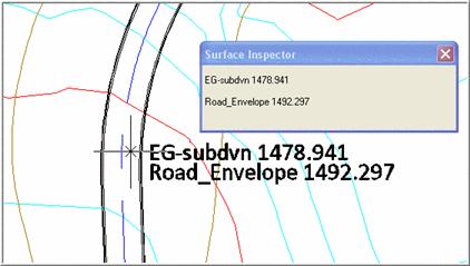 Pulldown Menu Location: Surface
Keyboard Command: surfvals
Prerequisite: Surface Model(s)