
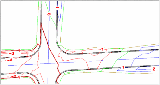
This command displays the amounts of
cut and fill between two surfaces by computing and displaying
cut/fill contour lines representing the amount of cut or fill along
that line. Cut contours are displayed in red (with negative
values), fill in blue (positive values), while the lines of zero
cut (the "daylight" lines) are displayed in green ("0"
labels).
The Use Color Ramp option
changes the color of the contours to be darker as the cut and fill
get deeper. Use the Draw Only Cut/Fill Daylight option to
draw only the daylight lines, indicating the areas where the two
surfaces intersect. The Daylight Tolerance setting controls
which contours are drawn in green.
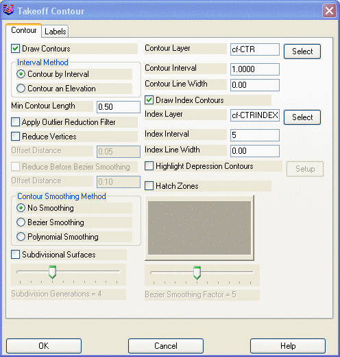
Cut/Fill Contour Settings:
You set the contour settings in the opening dialog by selecting the
Cut/Fill Contour Settings
button, which is comprised of the Contour and Labels tabs identical to those in
Triangulate and Contour.
Please refer to that command for details on the dialog options. You
may wish to designate alternate layer names for these sets of
contours to avoid overwriting previous contours on surface layers,
and generally you will set the contouring interval to 1 foot.
 Prompts
 Pulldown Menu Location:
Surface >> Cut/Fill Utilities
Pulldown Menu Location:
Surface >> Cut/Fill Utilities