This command creates an .SCT file from Carlson points in the
drawing. An .MXS file is needed to define the centerline and the
stations of the cross sections. The offsets for the cross section
points are derived from the perpendicular distance between the
centerline and the Carlson points. The cross section elevations
come directly from the elevations of the points. In order to be
included in a cross section, a Carlson point must be within the
offset tolerance distance of the cross section line.
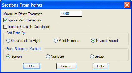
The order that the points within the Offset Tolerance at each station are used will of course determine the shape of the cross section. There are three ways for the collected points to be sorted. The Offsets Left to Right option sorts by the distance of each point from the CL. The Point Numbers option ignores that data, and instead sorts the points by their numbers. The Nearest Found option ignores both distance from the CL and point numbers and instead checks the horizontal and vertical proximity of the points to each other and sorts them based on this data. A powerful application of this method would be a survey of a tunnel where the points collected at each station were collected in a random order.
Choose MXS File to Process select file
Choose SCT file to Append/Write select
file
Enter the maximum offset tolerance <1.0>: press
Enter
Ignore Zero Elevations (<Yes>/No)? press Enter
This option filters out all Carlson points that have a zero
elevation.
Select points along the sections.
Select objects: pick the Carlson points
|
|
| Carlson points for use in creating Section file |
Pulldown Menu Location: Sections
Keyboard Command: sctpts
Prerequisite: Carlson points and an .MXS file
