


This command creates a template definition file (.TPL file) used primarily for modeling roadway, railway and other types of corridor designs.
 Template
files can then be applied through a variety of commands including
(but not necessarily limited to):
Template
files can then be applied through a variety of commands including
(but not necessarily limited to):
In the lower portion of the dialog box are four "list boxes" that list the elements of the template. The Surface elements are listed in order starting from the center of the template moving outward. The Subgrades are listed from top to bottom order. To add a template element, highlight the position in the list above where to insert the element. There is no limit to the number of Surface or Subgrade elements. The following types of objects can be utilized to create a template:
| Button | Description |
|---|---|
|
|
Grades - Typically, linear segments that defined paved surfaces such as roadway pavement, sidewalks and other linear surfaces that are "exposed to daylight." |
|
|
Curb - Typically, "formed" shapes that help control storm-water run-off. |
|
|
Median - Typically, "free-form" features such as "roll-over" medians or other types of traffic barricades. |
|
|
Subgrade - Subsurface material(s) that are used to derive "pavement" volumes (e.g. bituminous asphalt, aggregate base course, etc. |
|
|
Superelevation (Super) - Parameters that indicate how (and where) the template "grades" should elevate within curves or other areas of superelevation. |
|
|
Cut Slopes (Cut) - Specialized "grade" slopes that are used to "tie" the template to an existing surface when the elevation of the outermost point of the template is below ground. |
|
|
Fill Slopes (Fill) - Specialized "grade" slopes that are used to "tie" the template to an existing surface when the elevation of the outermost point of the template is above ground. |
|
|
Rights-of-Way (ROW) - Additional constraints utilized by the template in an effort to minimize the "footprint" of the disturbed limits of a cross-section relative to the right-of-way based on a given centerline. |
Additional categories of functionality include:

Percent: Specify this option when the "s" vertical displacement amount of a slope is specified relative to 100 horizontal units of measure.
Ratio: Specify this option when the "s" horizontal amount of a slope is relative to 1 units of measure vertically.
Vertical: Specify this option for an "undefined" (vertical) slope ("s") in which there is no horizontal component.
Slope: Indicate the "s" value relative to the type of slope selected above. Positive slope values indicate an increase in elevation along the grade segment; negative slope values indicate a decrease in elevation along the grade segment.
Linear: Specifies a constant slope along the grade segment.
Parabolic: Specifies a varied slope that gets steeper across the grade until it reaches the full specified slope at the end of the grade.
Horizontal Distance: Specify the horizontal distance component (positive values only) of the grade segment.
Pick: Prompts to select a linework segment or two points from the drawing to define the grade slope and distance.
ID: The ID (typically a two- or three-character identifier) serves four purposes:
Set: Displays a list of grade ID's from the current Template ID Library.

Curb Type: Select the general shape of the curb "plate" that best matches the curb you wish to define. If your curb does not conform to one of these shapes, you can also utilize the Median component.
Dimension Units: Indicate the desired units for the Curb Dimensions (e.g. feet, inches or meters in metric mode).
Integral Curb/Separate Curb: Indicate whether to draw the front line of the curb to separate the curb from the subgrade. For example, fully concrete pavements that contain a curb would be drawn with the "integral" curb option:

|

|
Rounding: Indicate the type (or amount) of "smoothness" that should be applied between curb faces.

|

|
Base Slope Type: The Base Slope Type of the curb can either be flat, set to the slope of the incoming grade or set to a user-specified slope. For the Match Crown method, you can use the Table option to define a lookup table of different curb slopes for different crown grades. For cases with part of the curb at a slope and part flat, you can use the Base Break Offset to set the transition position between sloped and flat. The Target setting for the slope controls which parts of the curb are sloped.
Curb Dimensions: Indicate the various dimensions (in units defined by Dimension Units) of the curb components.
Material: Indicate the name of the material for the curb for reporting purposes from commands such as Process Road Design.
ID: The ID (typically a two- or three-character identifier) serves four purposes as discussed in this ID discussion.
Set: Displays a list of grade ID's from the current Template ID Library.
Direction: This option controls which way the curb faces and is needed for divided roadway templates that have curbs facing both ways on either side of the road.
Load: Allows a previously saved curb (*.crb) "plate" to be opened for editing.
Save: Commits the current curb "plate" to a named curb (*.crb) file.
The Median is a flexible, closed figure defined in a clockwise direction. Each median point consists of an X and Y offset. The median must be closed and the program will automatically create the closing segment. The display shows the median in magenta and the grade lines in and out in green. For the display the grade in comes from the left and the grade out goes to the right. The median must define the Grade In point which is the point that ties into the incoming surface grade. Also the Grade Out point must be specified for where the surface grade continues out from the median. These Grade In and Grade Out points emanate from the starting or "from" position in the coordinate dialog where they are specified. Since a single median must be placed on the left or right side (and is typically not used symmetrically with right side same as left), you will need to offset the template centerline one-half the median width within the command Process Road Design in order to center the median. You will also have to move the "C/L" designation, to obtain centering, when using Draw Typical Template.

Skip Median at Stations without Adjustments: When enabled, this option creates the median only in the station ranges of a Template Point Profile and/or Template Point Centerline transitions.
Median ID: The ID (typically a two- or three-character identifier) serves four purposes as discussed in this ID discussion.
Set: Displays a list of grade ID's from the current Template ID Library.
Add (Edit): To enter the dimensions of the median, use the Add or Edit button to display a dialog box similar to that below:
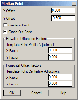
X/Y Offset: Provide the X/Y displacement of the median segment relative to the end of the previous median segment.
Grade In/Grade Out Point: Indicate if the median point is the position that accepts the incoming grade and/or generates the location for the out-going grade segment of the template.
Elevation Difference Factors: Controls how to apply Template Point Profiles. For Template Point Profiles, the program figures the amount of vertical adjustment between the transition profile and the normal profile. The amount of this vertical adjustment is multiplied by the adjustment factor and then added to the X/Y Offsets of the median point.
Horizontal Offset Factors: Controls how to apply Template Point Centerlines. For Template Point Centerlines, the program figures the horizontal adjustment between the transition centerline and normal centerline for Template Point Centerlines and applies this adjustment by the factors to the offsets.
NOTE: These adjustment factors allow for dynamic medians. For example, the height of a retaining wall could be controlled using a Template Point Profile and the median points for the vertical sides would have a Y Factor set to 1 to pick up the full vertical adjustment and the median points for the top and bottom edges would have a Y Factor of 0 keep those edges the same.
Remove: Deletes the highlighted X/Y Offset record in the list.
Up (Down): Changes the order of the highlighted X/Y Offset record in the list.
Pick: The Pick button prompts to pick a closed polyline from the drawing to define the median geometry.
Load: Allows a previously saved median (*.mdn) to be opened for editing.
Save: Commits the current median to a named median (*.mdn) file.
You can design a median for "mirroring" to create a centered effect, as illustrated in a paved "rumble strip" section as shown below. The only negative to this method is the appearance of a vertical line in the median plot.

Clicking the Subgrade button displays the dialog box below that permits you to establish "design" materials used to build the design project. Subgrade entries are displayed below the Grade entries and there can be any number of subgrades stacked below one another or side by side.

NOTE: The subgrade values for Horizontal Offset, Distance and Pivot Offset can be specified by Template ID points (consider using the Template ID Library to create a consistent set of template ID codes). For example, EP could be used in Distance to have the subgrade assume (and be controlled by) the width of the "EP" grade. Additionally, expressions can be used such as EP+BC to adopt the distance of the EP segment plus the distance of the BC segment. This is especially useful for template transitions so that if the width of the EP grade varies, the subgrade width will automatically adjust.
Slope Type: Indicate if the "bottom" of the subgrade surface should match the slope of the grade surface above it or if the subgrade slope should travel at a special slope value. Remember, a positive slope value increases in elevation further from the centerline while a negative slope value decreases in elevation further from the centerline.
Distance Direction: Indicate if the bottom of the subgrade moves away from (Out) or toward (In) the center of the template.
Intersect Surface: Indicate how the subgrade surface should "tie" into another component of the template to form a closed region:

Horizontal Offset: Indicate the distance (by numerical or para-metrical equation) from the template centerline where the subgrade should start. The subgrade moves straight down from this location the depth specified in the Vertical Offset.
Vertical Offset: Indicate the cumulative depth from the elevation of the specified Horizontal Offset plus the desired thickness of the subgrade material. For example, if 6" of a pavement subgrade has been defined and 8" of aggregate subgrade is desired upon which the pavement is built, the vertical offset of the aggregate would be specified as 14". The Match Existing Surface option adjusts the subgrade depth to match the existing surface which applies for road rehabilitation when the subgrade is overlaying the existing surface.
Units: If applicable, specify the desired units of measure for the Vertical Offset control described above.
Distance: Indicate the distance (by numerical or para-metrical equation) of the desired width of the subgrade to the point where the Intersect Slope should start.
Material: Indicate the name of the material for the curb for reporting purposes from commands such as Process Road Design.
Superelevation Settings: Indicate if special superelevation pivot points will be used:
Pivot Offset: Indicate the distance (by numerical or para-metrical equation) of the desired superelevation pivot point. This location allows the subgrade slope to break in superelevation independently from where the surface grade breaks. The subgrade will follow the superelevation slope from the centerline to the Pivot Offset. After the Pivot Offset, alternative slope factors govern.
Max Slope After Pivot: Indicate the maximum allowable slope for the subgrade once the Pivot Offset has been reached.
Slope Type After Pivot: Indicate how the slope of the subgrade after the Pivot Offset should be governed:
Clicking on the "Super" (superelevation) button provides an interface of how the template should behave in zones of superelevation via the Input-Edit Superelevation command.

Divided Road: When enabled, the Transition from Normal to Super (Inside Edge) controls will be enabled.
Transition from Normal to Super (Inside Edge): When enabled, identify (by Template ID point or para-metrical equation, e.g. EPI+2 or EPI-2) where superelevation pivot points (typically, inside edge of pavement) should occur for the High and/or Low locations of the Pivot Points for a Divided Roadway template.
Transition from Super to Normal (Outside Edge): Identify (by Template ID point or para-metrical equation, e.g. EP+2 or EP-2) where superelevation pivot points should occur for the High and/or Low locations of the Pivot Point for an Undivided Roadway template.
Max Percent Slope Difference: Indicate the maximum allowable grade difference between the segments on either side of the Pivot Point. Once this maximum allowable slope difference is achieved, template segments outside of the pivot point will elevate as a unit relative to the grade segment inside the Pivot Point.
Low Side Grades to Match Greater Super Slope: This option applies to the template grades that are outside the superelevation pivot point. When the superelevation slope becomes steeper than these outside grades, then these grades are adjusted to match the same super slope. You can adjust up to two additional grades past the superelevation pivot point. For example, consider a template where the superelevation pivot point is the EP grade and the next grade is a shoulder (SH) and you desire this first segment to adjust with the EP grade. Set the "Low Side Grades..." control to "1". If the regular SH slope is -4%, the SH will stay at -4% through the superelevation until the superelevation rate becomes greater than 4% (at this point, the SH crown has been removed). If the superelevation rate of the EP segment continues to 6%, the SH segment will steepen to -6% to keep the SH crown removed.
Pivot Super From Low/Inside Edge: Commonly used in Divided Roadway scenarios, when this option is enabled the elevation of the Inside Pivot Point relative to the design profile elevation is held fixed and segments outside of the Low/Inside Pivot Point are raised.

Superelevation About C/L with Low Side Grades... = 1 and Max Percent Slope Difference = 7

Superelevation About Inside Edge with Low Side Grades... = 0 and Max Percent Slope Difference = 7
Use the Cut button to define cut-slope treatments when the outermost point of the template is below existing ground.

Slope Type: Indicate the type of slope unit used for the actual Cut Slope(s)/Fill Slope(s).
Right Side Same as Left: When enabled, the cut-slope treatments of the Left side of the template will also be used for the Right side of the template.
Pivot at Subgrade: This option will position the cut pivot point where the bottom subgrade intersects the template grade. The ditch or up-slope conditions will then occur from this special subgrade "daylight" pivot point, instead of from the outer grade pivot point.
Smooth Slope Transitions: When enabled, this option will gradually transition the slopes from one range to the next. In the Cut Grades dialog box example above, if the depth is 6 feet the slope will be in transition between 4:1 and 3:1.
Slopes in Series: When disabled, a single slope is used based on the depth of the Cut Pivot Point. When enabled, each slope is used to its target depth until an intersection with the ground is reached. Each successive slope in the series starts from where the previous slope ended.
Repeat Slopes: When enabled, the pattern of Cut slopes will repeat until the sequence of slopes "daylight" with existing ground.
Cut To: In addition to cut slopes to specific Depths, the Cut To option can be used to have each cut slope intersect a surface from a Section (.sct) file (such as a Rock Section File). With Cut To -- Surface enabled, the Process Road Design command will prompt for the cut slope section file(s).
Bench Between Cuts: This option allows you to enter a "bench" pattern consisting of a width at a percent slope to be inserted between each cut slope. This option is commonly used in deep rock cuts as a means to help protect vehicles from loose/falling debris in the rock-cut areas.
Tie to Existing Section Point: When enabled, this option will tie the cut slope from the cut pivot point to either:
Tie ID: Indicate the desired identification where the slope intersects the Existing Surface. This is the same setting as under the Fill Grades dialog.
Tie to Set Offset: When enabled, this option forces the cut slope catch point to a specified fixed offset. This offset can be relative to the:
Cut Slope(s): There is room to specify up to five cut slopes that can be applied at specific depths. In a simple case of a single cut slope, supply the Slope value and leave the Depth and remaining Slope/Depth boxes blank.
Pick: These buttons prompt to select two points or a linework segment from the drawing to define the cut slope:

Slope to Rock: Indicate the slope that should be used when using a Rock Section File within Process Road Design.
Slope Order: Enable/Disable this toggle to switch between the two Slope Order modes for rock slopes:
Force Berm: When enabled, this option will apply the Berm (defined using the Fill icon) in cut instead of a ditch up to the Max(imum) Depth of cut.
Force Fill: When enabled, this option will make the template attempt to find a catch point with a specified Fill Slope even when the pivot point is in cut to a Max(imum) Depth in cut.
Minimum Depth for Ditch: When the Cut Pivot Point is shallower than this value, the ditch grade(s) will not be applied. To always apply the ditch grade(s) when in cut, specify a value of 0.
Ditch Grade(s) can be inserted between the Cut Pivot Point and the Cut Slope(s) as a means to further control and channel storm-water run-off. Ditch Grades are essentially identical to the Grades option used in the regular template. The location of the Cut Pivot Point is based on the outer-most Grade or Median segment. Consider one of the following scenarios:
The option you use is ultimately governed by how/where the Cut Pivot Point should be defined.
Edit Ditch: Highlight a desired ditch grade and use this option (or simply double-click on the ditch segment) to adjust its value(s).
Add Ditch: Use this option to add any number of ditch grades. See the Grades for information pertaining to the various controls.
Remove Ditch: Highlight a desired ditch grade and use this option to remove it from the ditch grade list.
Load Ditch: Recalls a previously saved ditch (*.DIT) file.
Save Ditch: Saves the current ditch geometry to a ditch (*.DIT) file.
Use the Fill button to define fill-slope treatments when the outermost point of the template is above existing ground. The options for Fill Slopes treatment are similar to those used for Cut and any difference(s) are noted below.
 Slope
Type: Refer to Cut -- Slope Type for information.
Slope
Type: Refer to Cut -- Slope Type for information.
Right Side Same as Left: Refer to Cut -- Right Side Same as Left for information.
Pivot at Subgrade: Refer to Cut -- Pivot at Subgrade for information.
Smooth Slope Transitions: Refer to Cut -- Smooth Slope Transitions for information.
Slopes in Series: Refer to Cut -- Slopes in Series for information.
Repeat Slopes: Refer to Cut -- Repeat Slopes for information.
Bench Between Fills: Refer to Cut -- Bench Between Cuts for information.
Tie to Existing Section Point: Refer to Cut -- Tie to Existing Section Point for information.
Tie ID: Refer to Cut -- Tie ID for information.
Tie to Set Offset: Refer to Cut -- Tie to Set Offset for information.
Fill Slope(s): Refer to Cut -- Cut Slope(s) for information.
Pick: Refer to Cut -- Pick for information.
Force Cut: When enabled, this option will make the template attempt to find a catch point with a specified slope even when the Pivot Point is in Fill. You can specify the Cut Slope to use and the Max(imum) Depth for the slope.
Force Ditch: When enabled, this option has two different methods to apply the Ditch Grades from the Cut definition when the Max(imum) Depth of fill has not been exceeded:
Use Guardrail: When enabled, this option will extend the last template surface Grade the specified SHD Extension distance when the Fill is greater than the Min(imum) Depth.
Use Berm: Berm Grades are the fill equivalent to Ditch Grades. The Minimum Depth for Berm Grades will only draw the Berm Grades when the Fill depth is greater than the specified value.
The ROW (Right of Way) icon brings up the dialog shown which provides several methods that help govern how/where Cut and Fill slopes interest existing ground. Right-of-Way data is stored in a Centerline (.CL) file as stations and offsets for the left and right sides of a centerline.

Limit Cut/Fill Slopes by ROW: When enabled, the Cut or Fill slope will become steeper in order to tie into the ground at the Right-of-Way offset. For example, if the Cut slope is 4:1 but this slope ties into the ground past the Right-of-Way, the slope will be modified to something steeper such as 3:1.
Extend Ditch for Tie at ROW: When enabled, this option allows you to tie the catch-slope into the original ground at the Right-of-Way offset by widening the lowest ditch slope along its slope until the Row-of-Way limit is attained. Common practice for the utilization of this option is to obtain additional fill material and/or for the placement of linear fences along the catch-slope (Right-of-Way).
Use Left/Right Retaining Wall: When enabled, the Cut or Fill slope will be applied until the Right-of-Way offset and will then tie into the ground via a vertical slope.
Offset to Left/Right ROW: Specify an additional "buffer" amount (if any) inside the Right-of-Way that is to serve as the desired Right-of-Way catch-point.
Left/Ride Side Display: Choose the type of catch-slope treatment (e.g.
Cut, Fill
or None) that should be
displayed in the dialog box preview of the
template.
NOTE: The appropriate Cut/Fill slope will be
applied to the cross-sections regardless of the Display
setting.
Super Elevation: Choose the type of superelevation (e.g.
Right, Left
or None) that should be
displayed in the dialog box preview of the
template relative to the specified Super
% amount.
NOTE: The appropriate superelevation will be
applied to the cross-sections regardless of the Display
setting.
Right Side Same As Left: When enabled, template geometry specified for the left-side of the template will be mirrored to the right-side of the template to create a symmetrical template. For unique geometry on either side of the template, disable this option and click/highlight in the desired side (Left vs. Right, Surface vs. Subgrade) to establish the desired geometry.
Profile Delta Z: This option applies a vertical offset to the profile when the template is processed. This vertical offset applies to a template that has an element at the profile position that makes the template different than the profile grade. For example, when the profile grade is along the centerline at the pavement level and the template has a curb or median that is 0.5 above the pavement, then set the Profile Delta Z to 0.5 so that the template matches the pavement grade after coming down from the 0.5 curb or median.
| Button | Action |
|---|---|
| "Pans" the Preview display of the template (same as a press/hold of the middle-button of a 3-button mouse). | |
| "Dynamic zoom" of the Preview display of the template (same as a "wheel roll" of a wheel-button mouse). | |
| Incremental "zoom in" of the Preview display of the template. | |
| Incremental "zoom out" of the Preview display of the template. | |
| "Zoom extents" of the Preview display of the template that fits/restores the content of the template into the Preview display. |
Move Up/Down: Highlight an element whose position you want to change and click the appropriate button to move the template element up or down through the other Surface or Subgrade items.
Edit: Highlight an element whose data you want to modify. Alternatively, double-click on the item to edit it.
Remove: Removes the highlighted element from the list.
Import Polyline: This option adds Grade element(s) to the template from a selected polyline via Command-line prompts.
Change Units: This option allows you to apply a scale factor to the distances in the template which can be used to convert between English- and Metric-based templates.
Save: Saves the current change(s) to the template (*.TPL) file.
Save As: Description of Control.
Draw: Refer to the Draw Typical Template documentation for information pertaining to this command.
Report: This option provides two different report formats:
Copy Left to Right: This action is essentially the same as the Right Side Same As Left in that it clones the current elements on the left side of the template to the right side of the template.
Select polyline: Select a POLYLINE, LWPOLYLINE or LINE entity whose X,Y geometry should be used for the Distance/Elevation change of a particular Grade element.
Pick centerline position on polyline [end on]: Pick the location of where the template centerline is relative to the entity selected above.
Pulldown Menu Location(s): Civil → Roads, Construction →
Roads, Takeoff → Roads
Keyboard Command: template
Prerequisite: None