This command optimizes earth movement from cut to fill between
existing and design surfaces. The earth movement is reported
separately by haul ranges which is useful when using different
types of earth movers such as dozers and truck/shovel.
Select inclusion and exclusion boundaries:
If an exclusion or inclusion boundary needs to be set for the
existing/design tins used in Cut/Fill Movement, first draw either
the existing of design tin to screen using the drawtri command,
then select boundaries from the screen when prompted. If no
exclusion or inclusion boundaries are selected, Cut/Fill Movement
will process the entire existing/design tin (though other options
such as auto size grid limits still apply).
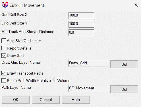
Cut/Fill Dialog options:
Grid Cell Size X: Determines the x value (width) of
generated cut/fill grid cells.
Grid Cell Size Y: Determines the y value (height) of
generated cut/fill grid cells.
Min Truck and Shovel Distance:
defines the truck and
shovel cutoff, see Report Details.
Auto Size Grid Limits:
Toggle on: The X and Y limits of the existing/design
surfaces are calculated then subdivided into grid cells according
to Grid Cell X and Y sizes.
Toggle off: User is prompted to window a section of the
existing/design surfaces. This windowed area is then subdivided
into grid cells according to Grid Cell X and Y sizes.
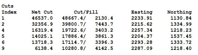
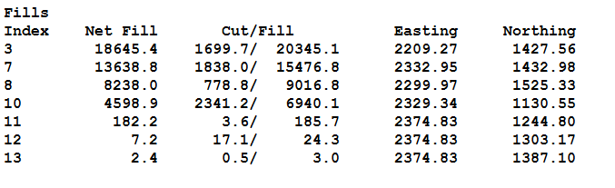
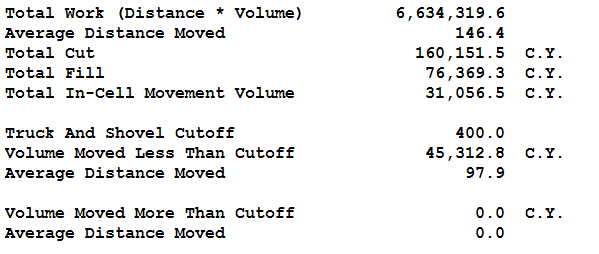
Report Details:
Toggle on: Total Work, Average distance moved, total fill,
and total in-cell movement volume is reported. In addition -- for
each cell -- net fill, a breakdown of cut and fill, easting and
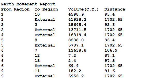
northing cell center locations is reported. Finally a breakdown of
transported cut is reported by From and To region, Total Volume
transported, and Distance cut is moved (excluding internal
transport).
Toggle off: Cut fill movement report reports total work
average distance moved, total fill and total in-cell movement
volume.
*Note: If a minimum truck and shovel distance greater than
0.0 is set the report will also include the Truck and Shovel cut
off as well as volume moved less that cutoff, volume moved more
than cut off and the average distance moved for both of these
values.
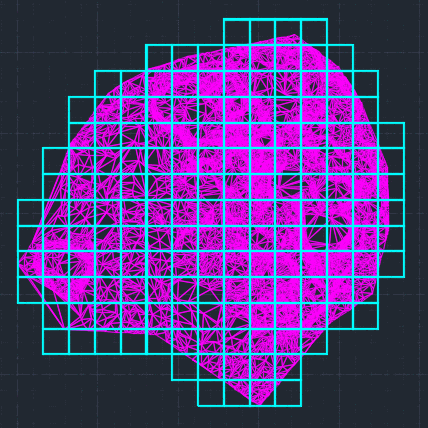
Draw Grid:
Toggle on: Draws a grid on "Grid Layer" (can be set using
Draw Grid Layer Name edit box) representing grid cells as defined
by Grid Cell Size X, Grid Cell Size Y and the Auto Size Grid Limits
toggle.
Toggle off: No grid is drawn.
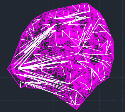
Draw Transport Paths:
Toggle on: Arrows representing the transportation of cut
from its initial cut cell to its destination fill cell are drawn to
screen according to the "Path Layer" (can be set using Path
Layer Name edit box). The Arrows can be scaled to show the relative
amount of transported cut by using the "Scale Path Width Relative
To Volume" toggle.
Toggle off: No arrows are drawn.
Pulldown Menu Location: Surface > Cut/Fill
Utilities
Keyboard Command:
cf_move
Prerequisite: Two surface models