Station Polyline/Centerline
This command will station a polyline or centerline file at a
given interval distance. The options for this command are set in
the dialog shown below. After setting the options, click OK on the
dialog and then pick the polyline or select the centerline
file. All settings can be saved as (.STA) files and loaded
for reuse, and for storing multiple stationing schemes.
Polyline/Centerline station labels are also dynamic, and so will
update when changes are made in the geometry.
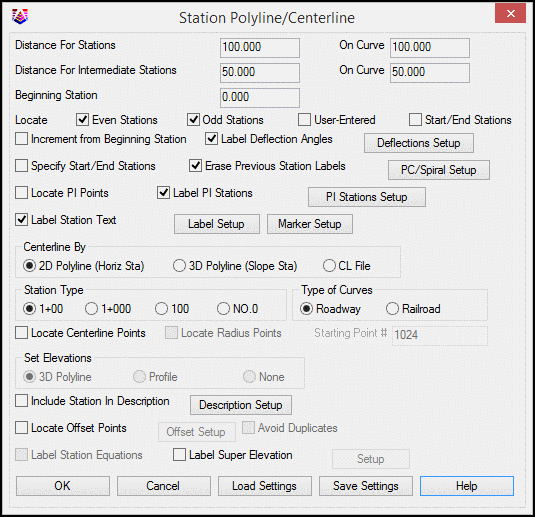
Distance for Stations is the primary interval for
stationing. On Curve allows for a different interval for curve
segments verses line segments.
Distance for Intermediate Stations is the intermediate
interval for stationing. On Curve allows for a different interval
for curve segments verses line segments.
Beginning Station is the beginning station of the centerline
for stationing.
Locate Even Stations labels the stations at the distance
interval (i.e. 2+00, 3+00, etc.).
Locate Odd Stations labels the non-interval stations at the
polyline/centerline end points and PC and PT points.
Locate User-Entered prompts you for individual stations to
label.
Locate Start/End Stations labels the Start and End Station
as specified when the option Specify Start/End Stations is
enabled.
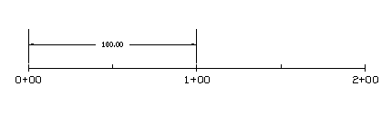
Without the Increment Station Labels from Beginning Station
option, the program increments the station labels from zero. For
example, if the station interval is 100 and the polyline starting
station is 145, then the program will label 2+00, 3+00, etc. With
this option active, the station labels are incremented from the
starting station. In this example, the program would then label
2+45, 3+45, etc.
Label Deflection Angles adds deflection angles to
centerlines without arcs. Settings for this are specified in the
Label Deflections Setup, accessed by the Deflections Setup
button.
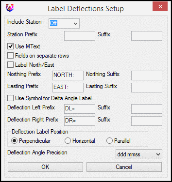
Include
Station sets the station name as None, Prefix or Suffix to the
deflection angle.
Station
Prefix and Suffix are added to the Station Label.
Use
MText option will create the deflection angle and associated
text as Mtext.
Fields
on separate rows will place each line of text on a separate
layer.
Label
North/East option adds a Northing and Easting coordinate to the
PI location.
Use
Symbol for Delta Angle Label adds a triangular shaped symbol as
a prefix to the deflection angle.
Deflection Label Position controls the postion of the label as
Perpendicular, Horizontal or Parallel
When Specify Start/End Stations is checked, only the
stations between and including the specified starting and ending
stations will be labeled. If locate centerline points and offset
points are toggled on, only points within the specified stations
will be located.
When Erase Previous Station Labels is checked,
previous station labels are erased when new ones are
generated.
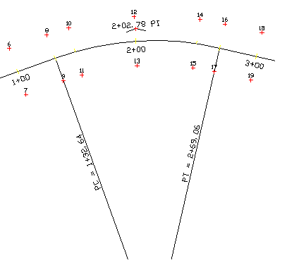
The PC/Spiral Setup PC button accesses the PC/Spiral Setup dialog, where settings
are controlled for lines and/or symbols and/or labels at the
starting and ending (PC and PT) stations of an arc of the
centerline as well as for the spiral special stations (TS, SC, CS,
ST).
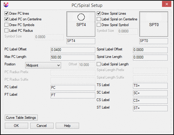
Draw
PC Lines controls whether lines are drawn from the PC and PT
points.
Label PC On Centerline when checked, the station of the PC
and PT will be labeled on the centerline as well as the PC and PT
lines. When not checked only the PC and PT lines will be
labeled.
Draw
PC Symbols controls whether symbols are placed at these
locations. If checked, the desired symbol is selected by
picking on the box to the right.
Label
PC Radius controls whether this point is labeled.
Max PC
Length controls the maximum length for the PC lines to be drawn
described above.
Position controls the placement of the PC and PT labels as
either the midpoint of the PC line or at a user defined offset from
the centerline.
Curve
Table Settings controls which elements will be labeled or
placed in a data table for both arcs and spirals as shown in the
Curve Table Setup dialog box.
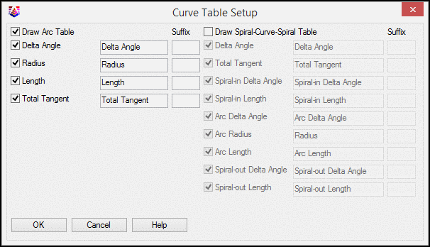
Draw
Arc Table when enabled, creates and draws a table containing
the arc information selected. Delta Angle, Radius, Length and
Total Tangent.
When Label PI Stations is checked, the PI station is
labeled at the PI point.
When Locate PI Points is checked a point will be created
at the PI of a horizontal curve graphically and written to the
active coordinate file.
When Label Station Text is checked, this command places
station text along the polyline at the angle of the corresponding
segment. After toggling this option on, the Label Setup button will
become available for selection.
The Label Setup controls the placement, precision, font
and size of station labels along the centerline.
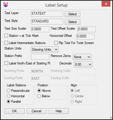
Text
Layer is the user-specified layer for text labels to be drawn
on.
Text
Style is the user-specified text style for labels.
Text
Size Scaler determines the size of the station labels. This
value multiplied by the horizontal scale setting in Drawing Setup
results in the size of the label. For example, if the horizontal
scale is set to 100 and the text size scaler is set to 0.10, the
station labels will be 10 units.
Text
Offset Scaler works like text size scaler above controlling the
distance the text labels will be offset from the centerline.
Station
+ at Tick Mark labels the station text along the polyline with
the '+' of the station text at the station's location on the
polyline. See Marker Set up for marker size manipulation
settings.
Horizontal Offset shifts the station label along the
centerline.
Label
Intermediate Stations: If the intermediate distance is the same
as the station distance then no intermediate station ticks or
labels will be drawn. For example, with the above entries and 0+00
for the first station the stations will be labeled with
descriptions as follows: 0+00 0+50 1+00 1+50, etc.
If the
Flip Text For Twist Screen setting is checked and the
drawing has been twisted using the twist screen command, the label
text will be flipped to read in the proper direction of the
stationing.
Station
Units when set to Miles divides the station values by 5280 for
creating the station labels. When set to Kilometers, it divides the
station values by 1000 for the labels.
Station
Prefix adds to the front of the station labels.
Remove
Zeros removes the specified number of least significant digits
from the station label if these digits are all zero.
Label
Northing/Easting of Starting Point adds this label information,
including prefixes and/or suffixes as specified.
Decimals determines the number of decimal places of the
stationing labels to be drawn for the odd stations and user entered
stations only.
Use
Label Stations to specify whether to label the stations
perpendicular or parallel to the centerline.
Specify
the Position of the station labels, either above or below
the centerline. This is only available when labeling stations using
the parallel option is enabled.
Align determines the alignment of the station label, either
left or centerline, centered along the centerline or to the right
of the centerline. This option is only available when using the
perpendicular option for station labels.
The Marker Setup options control the size of markers for
different station types as well as the layer the markers will be
drawn on.
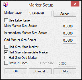
The
Marker Layer specifies which layer the station marks will be
placed.
Use Label Layer option sets the label for
the markers to be the same as that of the labels as set
above.
The
Half Size Main Marker, Half Size Intermediate
Marker and Half Size Odd Marker options draw a
perpendicular tick mark on only one side of the centerline.
Otherwise a full marker is drawn that goes on both sides of the
centerline.
Draw PI Lines option will draw a line in the
direction of both tangents, in and out of the PI at the size
designated in the PI Lines Size.
Specify whether to define the Centerline By picking a 2D
polyline or 3D polyline in the drawing or selecting a centerline
(.CL) file.
- Using a 2D Polyline
will result in horizontal distance stationing along the
polyline.
- Using a 3D Polyline
will result in the slope distance stationing along the
polyline.
- Using a CL File will
result in horizontal distance stations as with the 2D Polyline
option only a prompt for the centerline to use will display.
Use Station Type to specify the stationing format to
use.
Use Type of Curves to specify whether you are labeling a
roadway curve (arc definition) or railroad curve (chord
definition).
Locate Centerline Points will locate points and store
them in the current CooRDinate file.
Locate Radius Points will locate the radius points of any
arc segments.
Starting Point Number determines the starting point
number for the points to be located.
Vertical Exaggeration applies to Profile Polyline mode.
This factor is the ratio between the horizontal and vertical scales
on the profile grid.
There are two ways to Set Elevations for the centerline
points and offset points to be created.
- The 3D Polyline option
gets the elevation of the point from a specified 3D Polyline within
the drawing.
- The Profile option will
determine the elevation of the point based upon the same station in
the profile file. You will be prompted for the profile file to read
for the elevation reference.
- With the None option
selected, no elevations will be determined for the points.
When Include Station in Description is checked, the
station along the centerline will be included in the resulting
offset point description field.
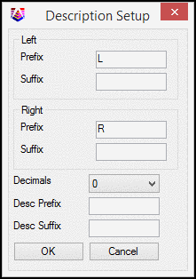
Left
Prefix or Suffix is added to the left offset label
Right
Prefix or Suffix is added to the left offset label
Decimals controls the label precision
Description Prefix is an optional user-specified prefix to be
added to the point description.
Description Suffix is an optional user-specified suffix to be
added to the point description.
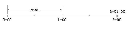
When Label Sta Equations
is checked on any station equation, contained in a centerline
(*.cl) file will be labeled. This option is only available when
stationing a centerline file (*.cl).
Locate Offset Points will create points at the specified
left and right offset distances from the centerline. Options for
setting the elevations and descriptions of the points are available
from the Offset Setup dialog.
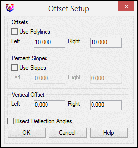
Use
Polylines allows you to select an offset reference polyline
Left and Right offsets allow a user defined offset
amount
Percent
Slopes allows you to project an offset grade based on a slope
from the corresponding centerline points.
Vertical Offset allows you to define a separate vertical offset
for the left and right horizontal offsets.
Bisect
Deflection Angles controls how the offsets are located at angle
points. When enabled, two offset points both 90 degrees from their
respect centerlines are located.
Label Super Elevation: This option labels the super
elevation transition stations as defined in the specified .SUP
file. You can choose which types of the transition stations to
label and set the prefix for each type.
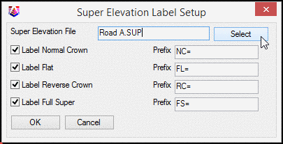
Use
Select to select a super elevation file (.SUP). This
file is created as part of the Roads Menu contained in the Civil
Module.
Prompts
Station Polyline Dialog
Polyline should have been drawn in direction of increasing
stations.
Select polyline that represents centerline: select a
polyline
|
|
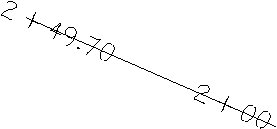
Closeup of Station + at Tick Mark option |
|
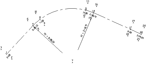
| Labels
with Label PC on Centerline checked on |
|
| Labels
set to perpendicular and Max Length of PC lines set to 75.0 |
|
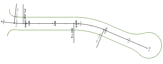
| Labels
with Draw PI Lines, Label PI Stations and Locate PI Points all
checked on |
|
|
Labels using Centerline By 2D Polyline (Horizontal
Station)
|
|
| Labels
using Centerline By 3D Polyline (Slope Station) |
Pulldown Menu Location: Centerline
Keyboard Command: stapl
Prerequisite: A polyline
or CL file