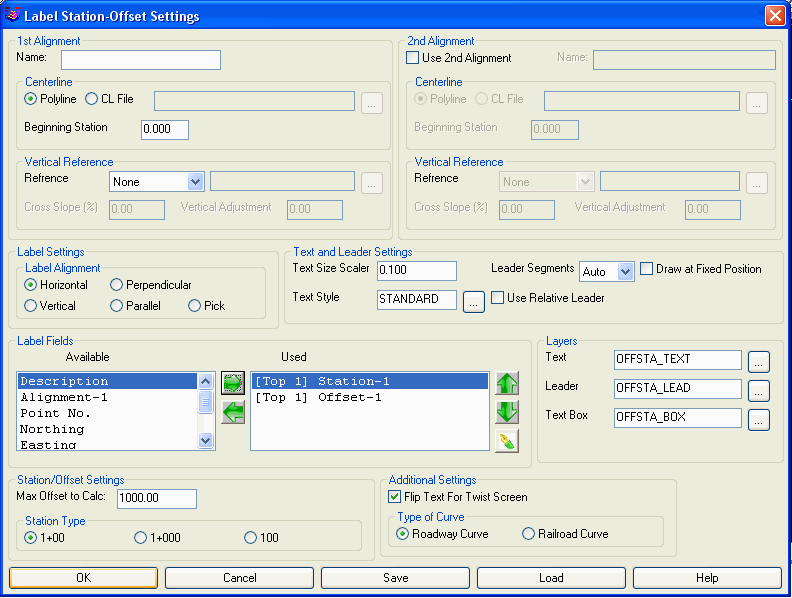
This command will compute and label the station(s), offset(s) and elevation(s) of a selected point or group of points or entities. Additional labels for the name(s) of the reference alignment(s) and description(s) can also be specified and placed to further annotate the point(s) that are selected.
A common usage for using dual alignments and profiles typically
involves the alignment and profile of a road coupled with the
alignment and profile of a pipe/utility.
Use 2nd Alignment: Enable this toggle if multiple alignments are to be used for the label(s) that will be placed into the drawing.
Name: Supply a label-friendly value for the name of the alignment (e.g. "King Street" or "Water Main"). The value(s) specified get assigned to the Alignment Label Field.
Centerline: Indicate the source (Polyline or Centerline File) for the reference alignment. If the Polyline option is selected, you will be prompted to select the polyline(s) after the OK button is pressed. If CL File option is selected, supply a valid path and file name for the centerline file or navigate to the file using the "File Picker" button. The Beginning Station will be determined from the selected Centerline File.
Beginning Station: Specify the beginning station of the centerline. The polyline should be drawn in the order of increasing stations. This control is not used when you use a centerline (.CL) file to define the centerline as the starting station of the centerline is stored in the .CL file.Vertical Reference: Indicate the source (3D Polyline, Profile File, Road Network or Surface File) for the reference elevation. With a Vertical Reference, there are label fields to label the Elevation Reference and Cut/Fill. With 3D Polylines, there will be an additional Slope Station available under the Label Fields in addition to the regular horizontal distance station. If the Profile option is selected, supply a valid path and filename for the profile file or navigate to the file using the "File Picker" button shown above. For the Road Network, specify the road network (.rdn) file with the "File Picker". With the Road Network method, the program will find the road design surface elevation for the specified points using all the road network design files including profiles, templates and transitions. For Surface File, the program will prompt for selecting a triangulation or grid surface model.
Cross Slope (%): Indicate the slope as a percentage to "travel" from the Vertical Reference. A value of 0 (zero) will not apply any cross slope from the reference elevation. Positive values will decrease the calculated elevation(s) and negative values will increase the calculated elevation(s).
Vertical Adjustment: Indicate the desired amount of vertical displacement that should applied to the calculated elevation. This is useful when deriving elevations for back or face of curb.
Label Alignment: Specify whether the labels should be Horizontal on the
screen, Vertical on the screen, Parallel to the Centerline,
Perpendicular to the Centerline, or user-specified by
Picking.
Text Placement Options: Controls how the leader is drawn
with the label. The Above/Below Leader method draws the leader
along the label. The After Leader draws the leader up to the
label.
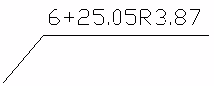 Above/Below Leader
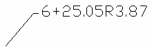
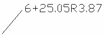 After Leader No Tick
Text Size Scaler: Determines the size of the labels. This value multiplied by the horizontal scale setting in Drawing Setup results in the size of the label. For example, if the horizontal scale is set to 100 and the text size scaler is set to 0.10, the labels will be 10 units.
Text Style: Specify the desired text style for the label.
Leader Segments: Specify the desired number of leader segments that should be allowed when constructing the label.
Use Relative Leader: Indicate whether successive labels placed into the drawing
should re-use the geometry of the initial leader placed with the
command.
Draw Leader Arrow: Indicate whether to draw an arrowhead on the
leaders.
Draw Line From Centerline: This
option draws a perpendicular line between the point and the
centerline. The Setback Offset option shortens the line and makes
gaps at the centerline and point ends. The Set Label Adjacent
option places the label along this line instead of at the leader
endpoint.
Draw At
Fixed Position: After you pick the first label position, the
rest of the labels will be placed at this same level. This option
applies to the Vertical and Horizontal Label Alignment
methods.
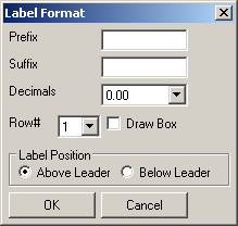
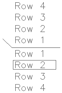
Label Fields: Use the green arrow buttons to specify the items that are to appear in the labels. As labels are "moved" from Available to Used, a Label Format dialog box particular to the label will appear that will allow for more precise display control. To subsequently edit each item, use the Format Editor button as shown below.

Layers: Specify the layer of each item that comprises the label.
Max Offset to Calc: Specify the maximum offset to calculate.
Truncate Station
at +: Removes the digits before the + in the station
labels.
Station Type: Specify the stationing format to use.
Station Units: When set to Miles
divides the station values by 5280 for creating the station labels.
When set to Kilometers, it divides the station values by 1000 for
the labels.
Reverse Text for Twist Screen: This
option changes the order of the labels to always read in order from
the centerline instead of in left to right order of the
screen.
Flip Text for Twist Screen: When this option is enabled, the label(s) will be flipped as necessary to adjust for the use of Twist Screen.
Offset Tolerance: For points with an offset greater than the specified tolerance, this option puts the labels in a separate layer. This option is a way to highlight points with offsets more than the tolerance. The separate Offset Tolerance layer can be setup to use a different color.Type of Curve: Specify whether the centerline is for a roadway or railroad. Stationing for Roadway Curves is measured along the curve length itself whereas stationing for Railroad Curves is measured along chord segments.
Save: Allows the current settings to be saved to a Station-Offset Settings (*.sos) file.
Load: Allows settings from a previously saved Station-Offset Settings (*.sos) file to be recalled for use.
Polyline should have been drawn in
direction of increasing stations.
Select Polyline Centerline
(Alignment-1): Pick the polyline
centerline This prompt will not appear if the Centerline
File option was specified.
Select 3D Polyline Profile
(Alignment-2): Pick the polyline
profile This prompt will not appear if the Profile File
option was specified.
Pick point or point numbers (SS for Selection
Set,G for Group,Enter to End): Pick a
point
Pick point to label: Pick a leader vertex point
Pick label alignment: Pick angle for the label This prompt will only
appear if the Pick option was specified.
Pick point or point numbers (SS for Selection
Set,G for Group,Enter to End): Press
Enter
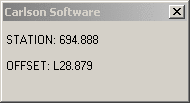
Real-time display of Station and Offset as you move the cursor.
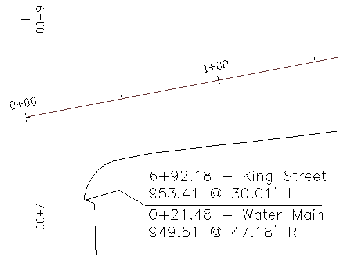
A sample label with a 2-segment leader.
Pulldown Menu Location: Centerline