Highlight Crossing Breaklines
Breaklines are lines or polylines that are used in surface
modeling to represent a feature such as a ridge, stream or curb.
Breaklines force triangulation and interpolation to occur between
the vertices of the breakline, which prevents any other
triangulation line from crossing the breakline. It is
important to avoid crossing breaklines in the surface model because
the program cannot force triangulation along both since holding one
will cross the other. Also the program cannot hold the
interpolation along both because the elevation at the intersection
point can be different for the two breaklines. For example,
consider a breakline going from 101 to 105 and another going from
107 to 109. If these lines had an intersection at the midpoint, the
elevation for one would be 103 and the other 108. This is an error
that needs to be fixed by the user because those two breaklines are
holding different elevations at the same point.
This command checks for intersections between the selected
breaklines and then identifies any crossing breaklines by
highlighting them. You can then edit these crossing breaklines
before doing surface modeling such as Make 3D Grid or Triangulate
& Contour.
Prompts
Ignore zero elevations [<Yes>/No]?
Reading points ...
Select surface entities to check.
Select objects: select polylines and lines
2915 found
Select objects: press
Enter to conclude selection
Reading points ... 4442
122 crossing breaklines are highlighted.
Use Report Formatter [Yes/<No>]? press Enter
Minimum delta Z to report <0.0>: press Enter
Add polyline vertices at intersections [Yes/<No>]?
press Enter
or
Found no crossing breaklines if there are none.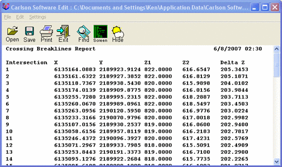 Pulldown Menu Location: 3D
Data >> Highlight 3D Polylines
Pulldown Menu Location: 3D
Data >> Highlight 3D Polylines
Keyboard Command: xbar
Prerequisite: Polylines