
The Scene Tab allows customization of the currently active scene's drawing options. The Scene Tab will be blank until you open a scene from the Project Tab using the View command.

Each scene maintains a tree-style list of the objects it contains as well as the graphical settings for those objects. Upon first opening a scene and selecting the scene tab, the scene itself will be selected in the tree structure and the Lights properties of that scene will be visible. To modify the graphical properties of an object, select that object from the tree list and the properties panel will update to show the current properties for that item.
There are five types of graphical properties that an object can have:
If an object has more than one of these properties, then they will be arranged in a tabbed notebook style similar to how the Project Manager is organized. Aside from Lights properties, there exist two modes for each property type:
These relate to the two different types of drawing modes that the Point Cloud Viewer operates in.
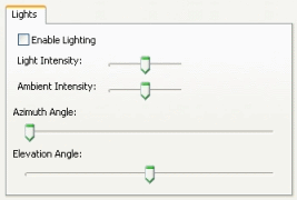
Lighting can be used to help enhance the visibility of changes in a surface that might be too minor to detect in certain color modes. Keep in mind that enabling lighting will sacrifice performance for this increased image clarity. There are two parts to the lighting functionality, the directional light and the ambient light.
Directional Light
Light Intensity Controls the intensity of the directional light, which is a light, positioned to simulate the effect of a distant light source like the sun. Azimuth Angle Controls the angle of the directional light source with respect to the z axis. Elevation Angle Controls the angle of the directional light source with respect to the xy plane. Ambient Light
Ambient Intensity Controls the intensity of the ambient lighting, which is the base light level that affects everything regardless of the surface normal.

Vertex, Edge, and Face properties control how an object's vertex, edge, and face elements will be drawn. The visibility of these elements can be toggled with the Show checkbox, and their size can be modified in the Size text box. There is an additional Show Front and Show Back options for edges and faces that pertain specifically to drawing edges or faces that face towards the mesh's normal or away from the meshes normal (usually the positive z axis). The Single radio button allows you to give the edges/vertices of the currently selected object a solid color, instead of whatever coloring mode you might already have applied to the object. The new color can then be specified by clicking on the Color button. The Smooth option in the performance panel tells whether to enable antialiasing on the vertices or edges to make them look smoother at the cost of performance.


The Text properties page controls how the viewer will draw an
object's text elements. It contains similar controls to the Vertex,
Edge, and Face controls, but also has a couple options that pertain
specifically to the text's alignment. Changing the alignment will
not change the origin of the text, merely how the text is displayed
in relation to that origin. Additionally, some objects can have
several text elements, so you will have to specify which text
attribute you want to modify in the Attribute drop down
box.

The ability to hide regions of a scene can be performed
by:
Note: This option is only available when using the 3DTK
Engine.
